Process and Apparatus for Sealing Wellhead Leaks Underwater or On Land

a technology for sealing equipment and leakage wellheads, applied in the direction of liquid transfer devices, sealing/packing, borehole/well accessories, etc., to achieve the effect of rapid solution

Inactive Publication Date: 2013-10-17
CORDELL STEVE
View PDF46 Cites 1 Cited by
  • Summary
  • Abstract
  • Description
  • Claims
  • Application Information

AI Technical Summary

Benefits of technology

[0004]Summary of the Apparatus and Method: The sealing apparatus is best described as a curtain, composed of layers of the strongest materials available and heavily weighted on its circumference. The curtain can be laid on or over the leak in one layer or successive layers. The method consists of optionally roughly preparing the base of the seabed, or the ground if the leak is on land, to give the sealing curtain a good base for laying it over the leak. The first curtain is laid over the leak, and then in stages, cement is poured inside of the weighted circumference. This method allows for the curtain to be weighted down with cement with none or very little of it being blown away by the forces of liquid or gas exiting the leak (FIG. 2). In the simplest method, the leaking fluid or gas will cause part of the curtain to flutter no matter how heavy the original weighting is. The flutter can be mostly eliminated by installing redirect mechanisms on the curtain. In this manner, fluid or gas under pressure will be allowed to escape or to be redirected via pipes, tubes or other means. This takes pressure off the curtain and the weighting will thus be simplified.
[0010]There are two radial reinforcements that may be required to ensure that the curtain remains circular at the weighted lip, and that the complete curtain surface remains robust. The first is a set of flexible, spring-loaded bars that allow the somewhat folded curtain to sink more rapidly from the water surface and to keep it circular over the well pipe. It is opened before the seabed is reached. For land applications, it will aid in transporting the weighted curtain to its destination wellhead and when placing the curtain near or within a drilling rig (Ref. 1) The second curtain includes a web of steel cables that will ensure that the curtain has even more strength than the materials described above (Ref. 2). The cables might be used for quick adjustment of the rim to be somewhat out-of-round if the seabed or land conditions require it. Both of the reinforcement apparatus are “heavy-duty”, otherwise they would be considered ubiquitous and require no further description here.
[0014]The invention provides for a rapid solution for sealing spills, since all materials used for the construction of the curtain are readily available, and all of the individual materials can be stored for years until use. Even though the finished curtain is extremely heavy, any of the world's heavy-duty aircraft can transport together a small curtain and all elements for a large curtain to any port nearby a spill. The large curtain can be erected and prepared for transport to the local spill site within two days if a medium-sized crane is available.

Problems solved by technology

Even though the finished curtain is extremely heavy, any of the world's heavy-duty aircraft can transport together a small curtain and all elements for a large curtain to any port nearby a spill.

Method used


Image

  • Process and Apparatus for Sealing Wellhead Leaks Underwater or On Land
  • Process and Apparatus for Sealing Wellhead Leaks Underwater or On Land
  • Process and Apparatus for Sealing Wellhead Leaks Underwater or On Land

Examples


Embodiment Construction

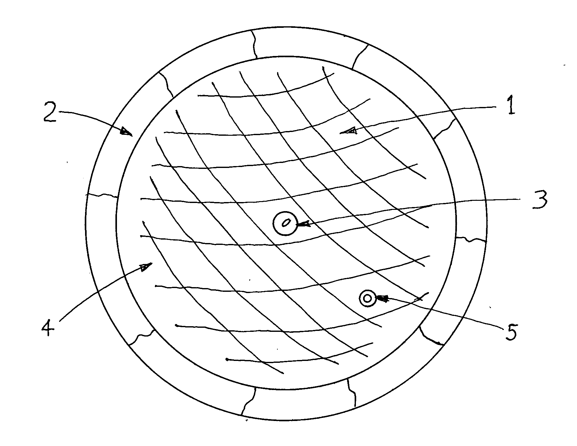
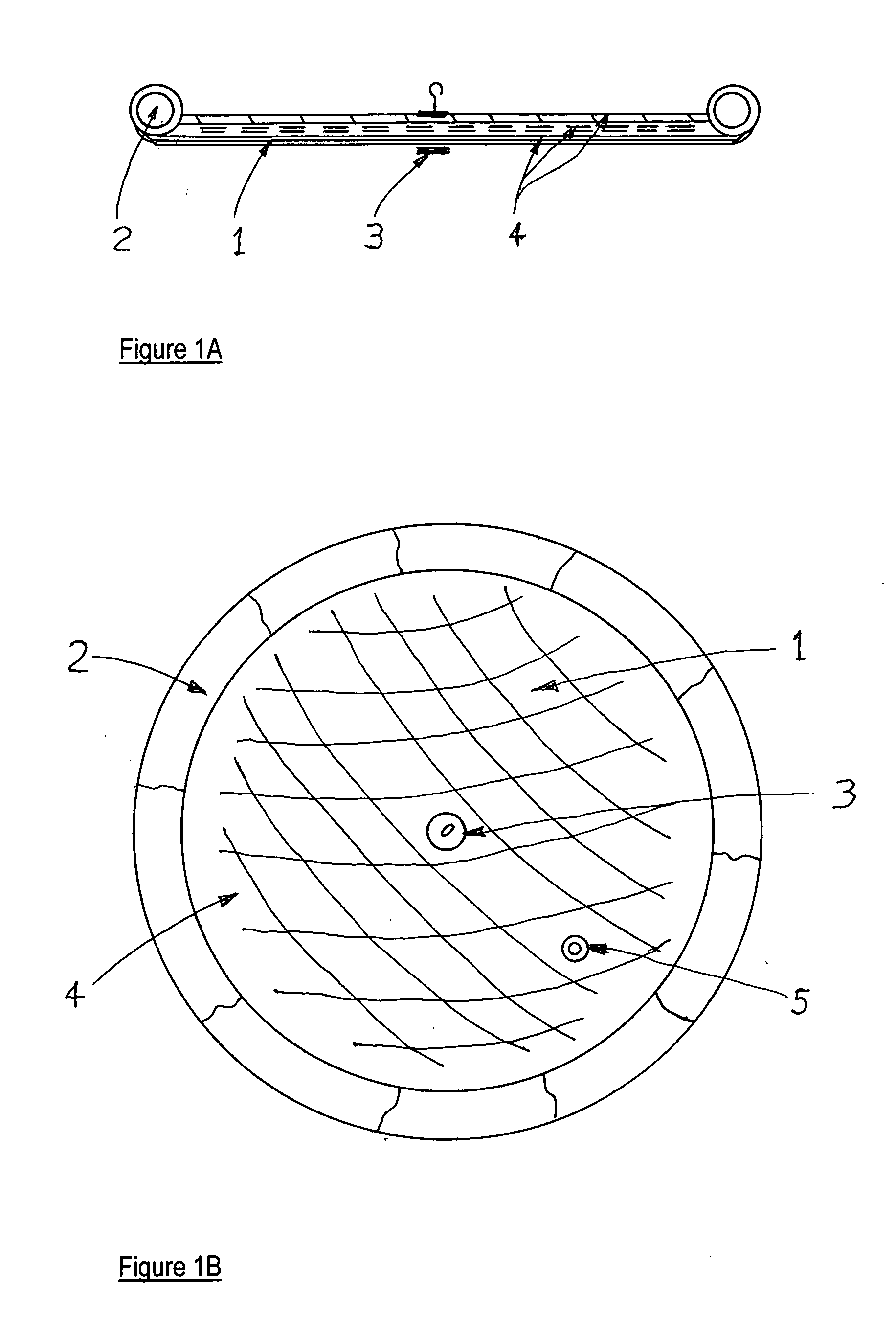
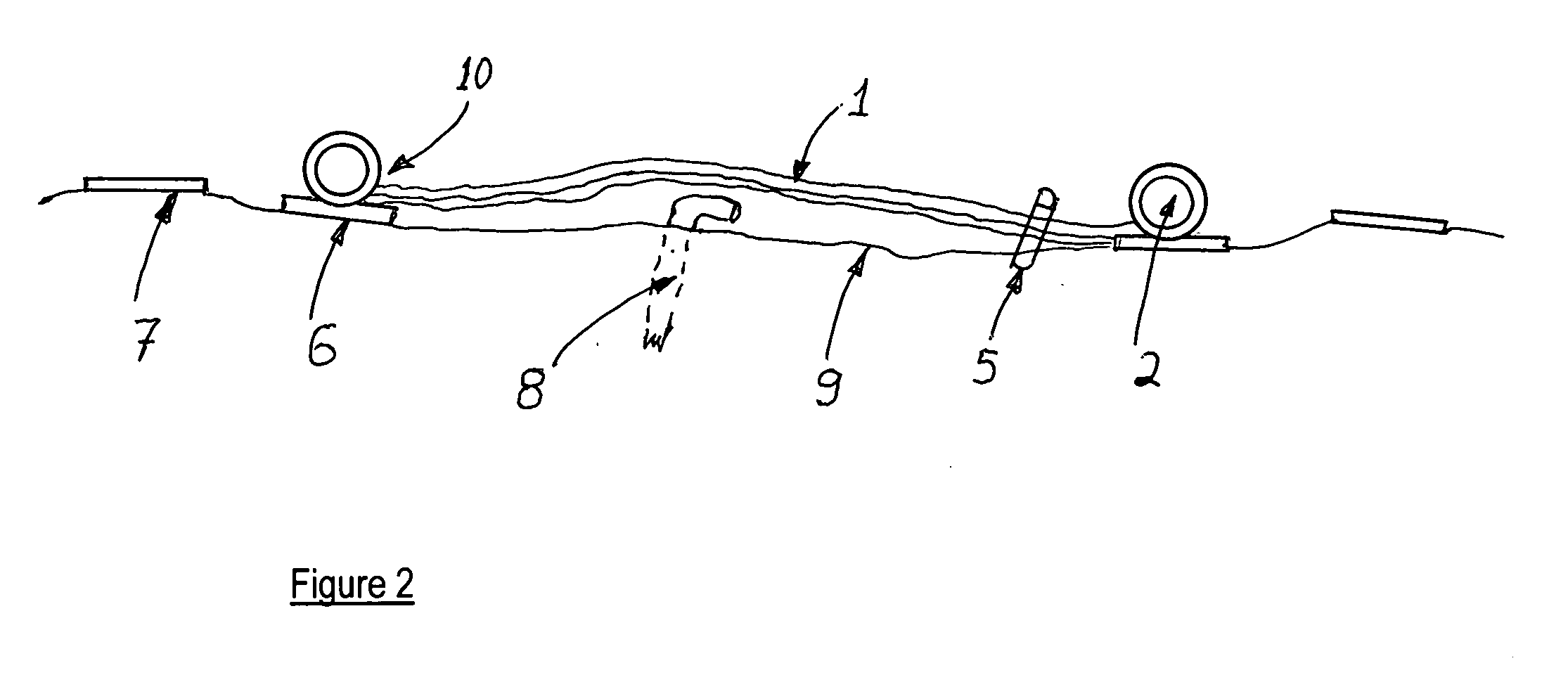
[0017]FIGS. 1A and 1B are two views of the apparatus and they are scaled alike; the numbers indicate the exact elements. The curtain 1 is integral with the peripheral weights 2. In FIG. 1B, the sections of weights 2 are clearly shown as separate weights and they are rolled up into the shown position on the periphery by using extra material when the curtain is laid out as a circle and its peripheral few feet are sliced for this purpose. No heavy duty rapping cables or webbing are shown on the round weights. The three layers 4 shown in FIG. 1A are indicated by three arrows and are only an example of one possible sandwich of curtain layers; in the FIG. 1B top view, the layers cannot be drawn but is also indicated as 4. The carrying hook 3 is shown with its connection flanges in both views. Only one redirection valve 5 is shown in FIG. 1B, and it is also shown in FIG. 2 as being capped on both ends to keep cement and other debris from entering the top connection section.

[0018]FIG. 2 is ...


PUM


Abstract

The sealing of underwater and above ground leaks of materials such as petroleum, mud, gas and finely divided solids from wellheads, pipelines and other natural or man-made works is accomplished by placing over the leak a heaviest duty, leak-proof, weighted curtain whose shape and size allow the curtain to be filled in place with cement or other heavy materials, thus effectively sealing the outflow of the materials.The curtain can optionally be fitted with one or more redirection valves to drain off and capture the materials under pressure, for example to transport oil, during and even after the sealing process, from a seabed wellhead leak to a surface ship. An optional second, larger curtain fitted with through-channels with stopcocks can be placed over the first curtain, and the lower valves and through-channels can be connected to continue the transport of materials.Preparation of the sealing sight is minimal, ideally consisting of forming a continuous circular path to more carefully mate the curtain's peripheral-weights with the ground or seabed terrain. If a wellpipe or other obstacle might damage the curtain, or vice versa, the wellpipe would be modified, and / or an optional self-expanding support attached to the curtain underside can protect the curtain during its cement-filling weighting process.

Description

FIELD OF THE INVENTION [0001]The and apparatus off intended or unintended leaks, gushers and flows of gas, mud, petroleum, other fluids and finely divided solids on land, on the seabed, or near land or the seabed, whereby the sealing apparatus may redirect the flow of fluid or gas to pipes, tanks or other holding or transporting means or vessels.BACKGROUND OF THE PRIOR ART[0002]This did not function on the British Petroleum leak, and over time the conventional method of sealing with a cap on the pipe protruding from the well did function. During the many unsuccessful trials, weeks went by and the leaking petroleum continued to spill out into the sea.[0003]Method and apparatus for sealing underwater fluid spills, & redirects fluid to ships. Sealing spills in the past (e.g. BP in Gulf) was by pouring fast-setting cement on the spill. For BP the cement dispersed! Invention uses cement indirectly and securely over impervious, weighted curtain.SUMMARY AND OBJECTS OF THE INVENTION[0004]Su...

Claims


Application Information

Patent Timeline
Patent Type & Authority Applications(United States)
IPC IPC(8): B67D99/00
CPCB67D99/00E21B33/02E21B43/0122
Inventor CORDELL, STEVE
Owner CORDELL STEVE
Why Eureka
Try Eureka