
Optical Mode Conversion Using Intermodal Cherenkov Radiation

a technology of intermodal cherenkov radiation and optical mode, applied in the field of optical mode, can solve the problems of high power of coating glass components and moving mechanical systems, prohibitive cost and maintenance problems, and low packing density of the cores in the bundle, and achieve the effect of high optical density

Active Publication Date: 2013-10-17
OFS FITEL LLC
View PDF3 Cites 9 Cited by
  • Summary
  • Abstract
  • Description
  • Claims
  • Application Information

AI Technical Summary

Benefits of technology

The patent describes a new type of laser combiner that overcomes some of the problems of previous designs. It uses a two-sectional approach, with a first tapered section that bundles together multiple input fibers. This section is connected to multiple lasers or optical sources to allow for efficient combining of optical power. The design of the multiple cores allows for a taper ratio of at least 3, while maintaining a low NA and preventing interaction between modes and the outer boundary. The tapered end of the first section can then connect to an output fiber or amplifier for concentrated high power light. The second tapered section includes a bundle of multimode fibers or cores to further reduce the size of the output beam. Overall, this new design provides more efficient and focused combining of optical power.

Problems solved by technology

As can be expected, issues occur when trying to use coated glass components and moving mechanical systems with high powers.
These details can create prohibitive cost and maintenance problems.
While multiple fibers can be bundled together and coupled to an output fiber with a large, multimode core, the packing density of the cores in the bundle is typically very low.
Bundling such fibers will result in significant reduction in the brightness of the optical source when coupled into the common output fiber.
While tapering of the fiber bundle will reduce the separation between cores and increase the packing density, there is a limit to the degree of tapering which may be used before the optical power in the individual cores either leaks out of the core or begins to couple into adjacent cores.

Method used


Image

  • Optical Mode Conversion Using Intermodal Cherenkov Radiation
  • Optical Mode Conversion Using Intermodal Cherenkov Radiation
  • Optical Mode Conversion Using Intermodal Cherenkov Radiation

Examples


Embodiment Construction

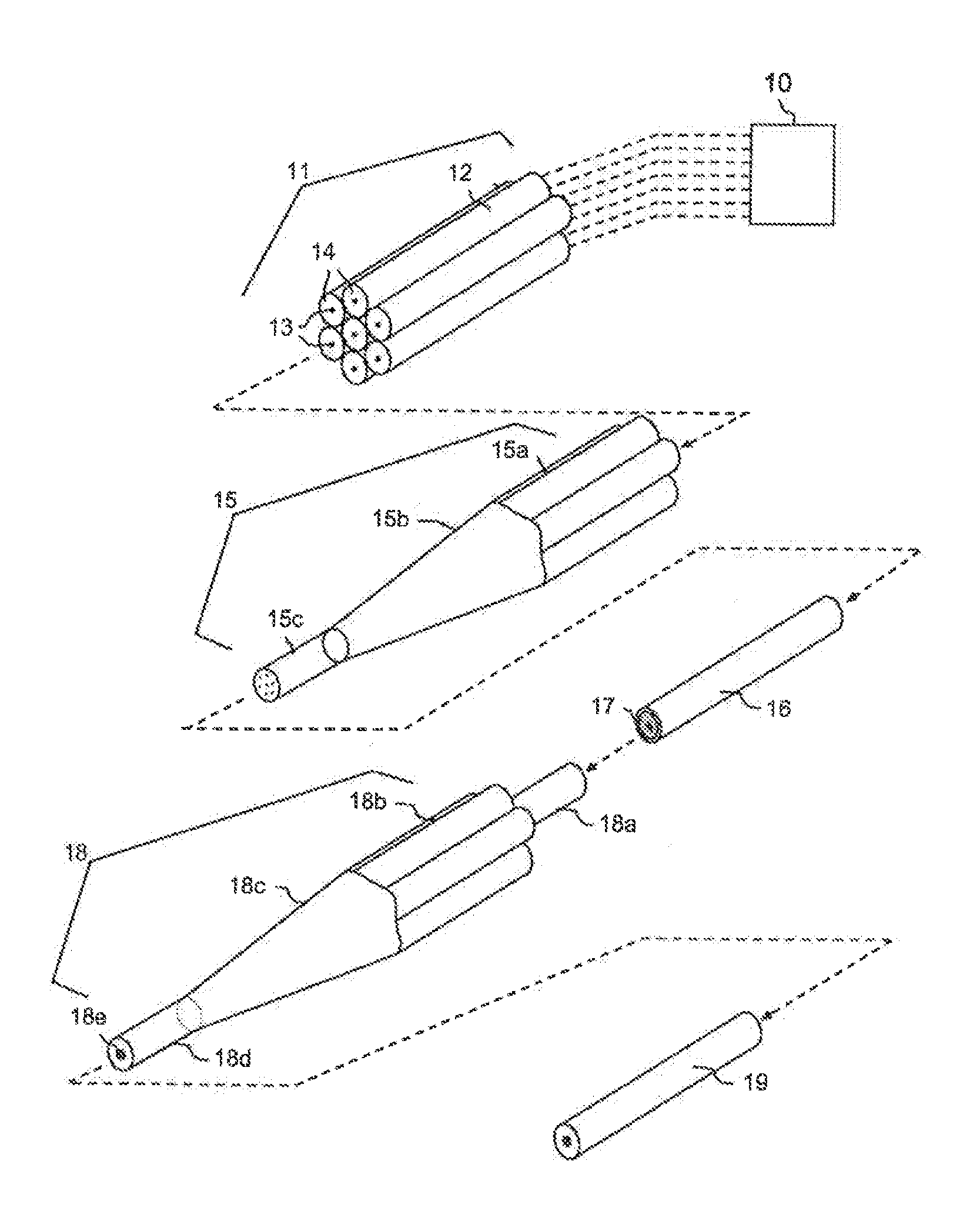
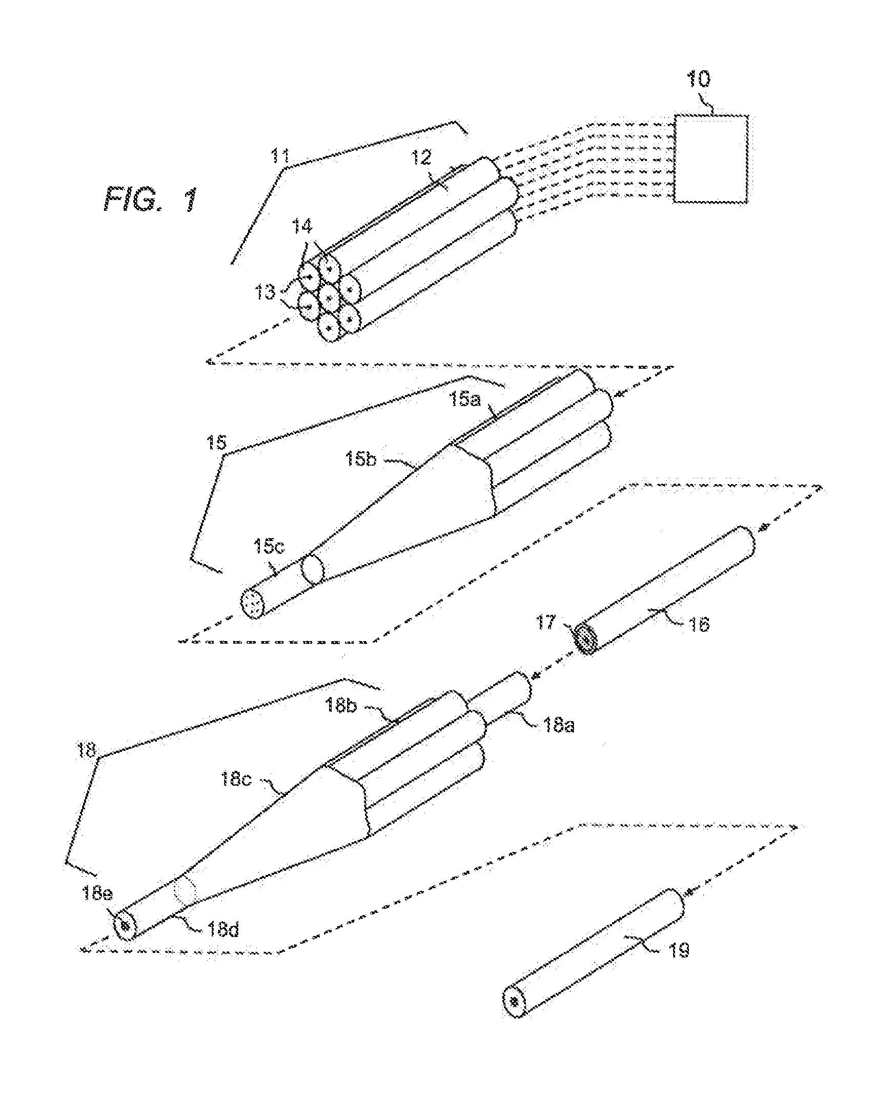
[0022]Referring to FIG. 1, an array of lasers is shown at 10. In the illustration shown here, as an example, seven lasers are shown and the laser combiner is designed to combine the outputs from these seven lasers into a single high power source. As this embodiment is but one example of the scope of this invention, the number of laser sources being combined may vary widely. A laser combiner according to the invention will combine at least two laser outputs using at least two tapered fibers. More preferably, the number of sources or fibers is between 5-30. As one objective of the present invention is to produce a high power source, the lasers 10 are typically high power lasers. In an all-fiber implementation, the lasers 10 can be rare earth doped optical gain fibers, for example, Ytterbium doped gain fibers. However, any suitable array of laser sources may be used. Referring again to FIG. 1, the lasers 10 are shown schematically coupled to an array 11 of delivery fibers 12. Each fibe...


PUM


Abstract

Embodiments of the present invention generally relate to laser combiners, and more specifically, to all-fiber devices that combine optical laser power from multiple separate sources such as lasers or amplifiers. In one embodiment, a method of manufacturing a combiner device comprises: positioning an plurality of fibers into a bundle of fibers; drawing the bundle of fibers to create a tapered section, the tapered section having a first outer diameter at an input end, a second outer diameter at an output end, and a taper ratio of at least three; wherein at least one of the fibers of the bundle of fibers comprises an optical waveguide configured for propagating an optical mode from the input end to the output end, and wherein a mode field diameter of the optical mode at the input end is substantially the same as the mode field diameter at the output end.

Description

CROSS-REFERENCE TO RELATED APPLICATIONS[0001]This application is a continuation application of U.S. patent application Ser. No. 12 / 760,547, filed Apr. 14, 2010, entitled “Fiber Based Laser Combiner,” which claims the benefit of Provisional Application Ser. No. 61 / 168,952, filed Apr. 14, 2009, the respective disclosures of which are incorporated herein by reference in their entireties.BACKGROUND OF THE INVENTION[0002]1. Field of the Invention[0003]Embodiments of the present invention generally relate to laser combiners, and more specifically, to all-fiber devices that combine optical laser power from multiple separate sources such as lasers or amplifiers.[0004]2. Description of Related Art[0005]In applications involving high power industrial lasers, fiber-based systems are increasingly attractive. Typically constructed from Ytterbium-doped gain fibers emitting in the 1060 nm wavelength band, fiber lasers with single-moded beam quality are limited to powers in the 200 to few kW range....

Claims


Application Information

Patent Timeline
IPC IPC(8): B29D11/00
CPCB29D11/00663G02B6/255G02B6/262G02B6/2804H01S3/067H01S3/1618H01S3/2383H01S3/094007H01S3/094019
Inventor HOLLAND, WILLIAM R.TAUNAY, THIERRY F.
Owner OFS FITEL LLC
Learn More