Method, circuit breaker and switching unit for switching off high-voltage DC currents

a high-voltage dc current and switching unit technology, applied in emergency protective circuit arrangements, air-break switches, relays, etc., can solve problems such as residual current flowing

Active Publication Date: 2013-10-24
HITACHI ENERGY SWITZERLAND AG
View PDF6 Cites 29 Cited by
  • Summary
  • Abstract
  • Description
  • Claims
  • Application Information

AI Technical Summary

Benefits of technology

[0006]An exemplary embodiment of the present disclosure provides a method for switching off a high-voltage DC current from a voltage source delivering a nominal voltage by means of a circuit breaker, which includes a semiconductor switching assembly and at least one mechanical switch in series. The semiconductor switching assembly includes a plurality of semiconductor switches and a plurality of arresters in parallel to the semiconductor switches. The exemplary method includes switching off the semiconductor switching assembly to reduce current in the circuit breaker to a residual current, and switching off the residual current by means of the mechanical switch. The arresters have an added threshold voltage exceeding the nominal voltage. The mechanical switch is arranged in a resonant circuit configured to generate an oscillating current through an arc in the mechanical switch after switching off the semiconductor switching assembly and opening the mechanical switch. The oscillating current has an amplitude exceeding the residual current such that at least one current zero crossing can be generated in the arc of the mechanical switch. The method also includes extinguishing the arc during the current zero crossing.
[0007]An exemplary embodiment of the present disclosure provides a method for switching off a high-voltage DC current from a voltage source delivering a nominal voltage by means of a circuit breaker, which includes a semiconductor switching assembly and at least one mechanical switch in series. The semiconductor switching assembly includes a plurality of semiconductor switches and a plurality of arresters in parallel to the semiconductor switches. The exemplary method includes switching off the semiconductor switching assembly to reduce current in the circuit breaker to a residual current, and switching off the residual current by means of the mechanical switch. The arresters have an added threshold voltage exceeding the nominal voltage. The residual current is below 20 Ampere.
[0008]An exemplary embodiment of the present disclosure provides a circuit breaker for switching off high-voltage DC currents of a nominal voltage. The exemplary circuit breaker includes a semiconductor switching assembly including a plurality of semiconductor switches and a plurality of arresters in parallel to the semiconductor switches. The arresters have an added threshold voltage exceeding the nominal voltage. The exemplary circuit breaker also includes a mechanical switch arranged in series with the semiconductor switching assembly. In addition, the exemplary circuit breaker includes a resonant circuit including a capacitor and an arc gap of the mechanical switch, where the capacitor is arranged in parallel to the mechanical switch. The circuit breaker is configured to switch off the semiconductor switching assembly to reduce current in the circuit breaker to a residual current, and switch off the residual current by opening the mechanical switch. The mechanical switch is arranged in the resonant circuit which is configured to generate an oscillating current through an arc in the mechanical switch after the semiconductor switching assembly is switched off and the mechanical switch is opened. The oscillating current has an amplitude exceeding the residual current such that at least one current zero crossing can be generated in the arc of the mechanical switch. The arc is extinguished during the current zero crossing.

Problems solved by technology

Interruption of direct currents (DC) is one of the major challenges for the realization of multi-terminal DC networks (MTDC).
One drawback of this type of arrangement is the fact that, when the switches are switched off, a residual current continues to flow.

Method used


Image

  • Method, circuit breaker and switching unit for switching off high-voltage DC currents
  • Method, circuit breaker and switching unit for switching off high-voltage DC currents
  • Method, circuit breaker and switching unit for switching off high-voltage DC currents

Examples


Embodiment Construction

[0015]Exemplary embodiments of the present disclosure provide a method and circuit breaker that allow for a high-voltage DC current to be completely switched off.

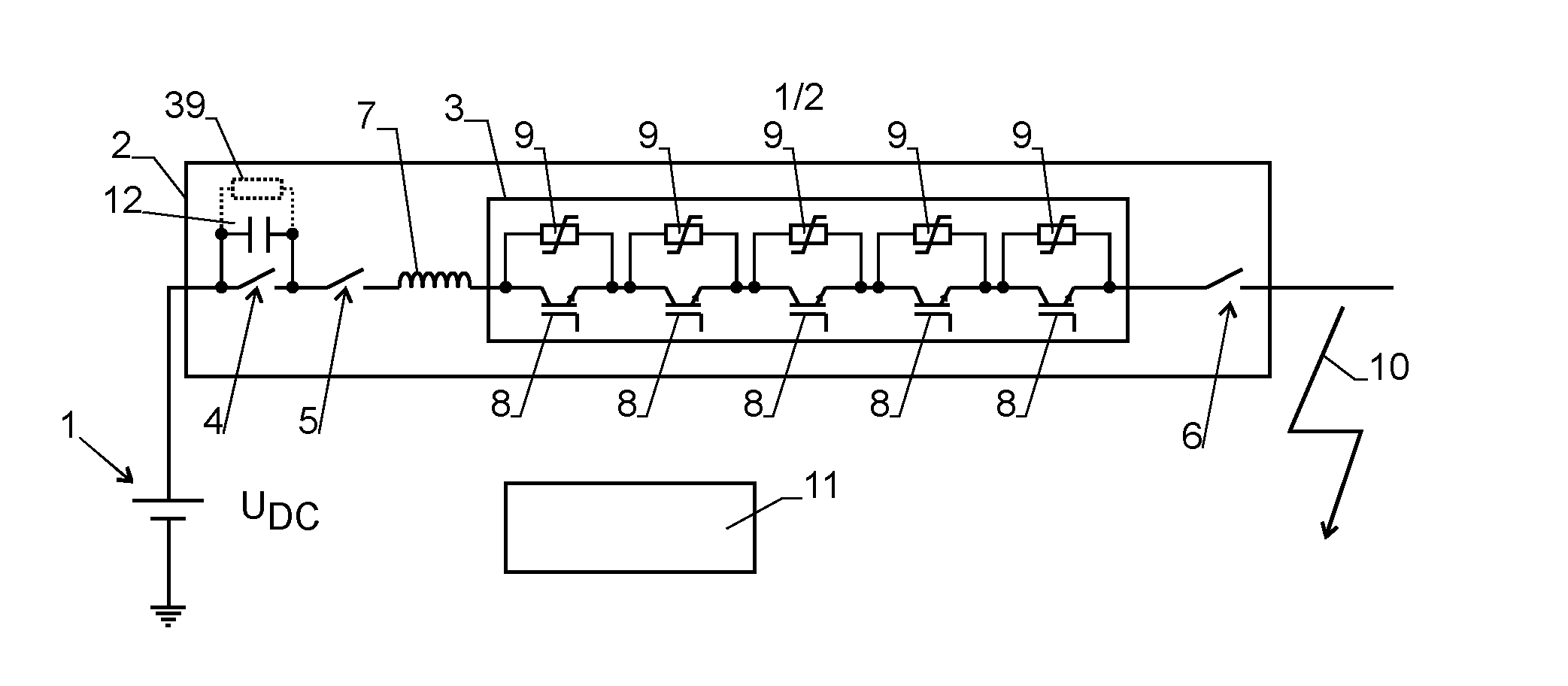
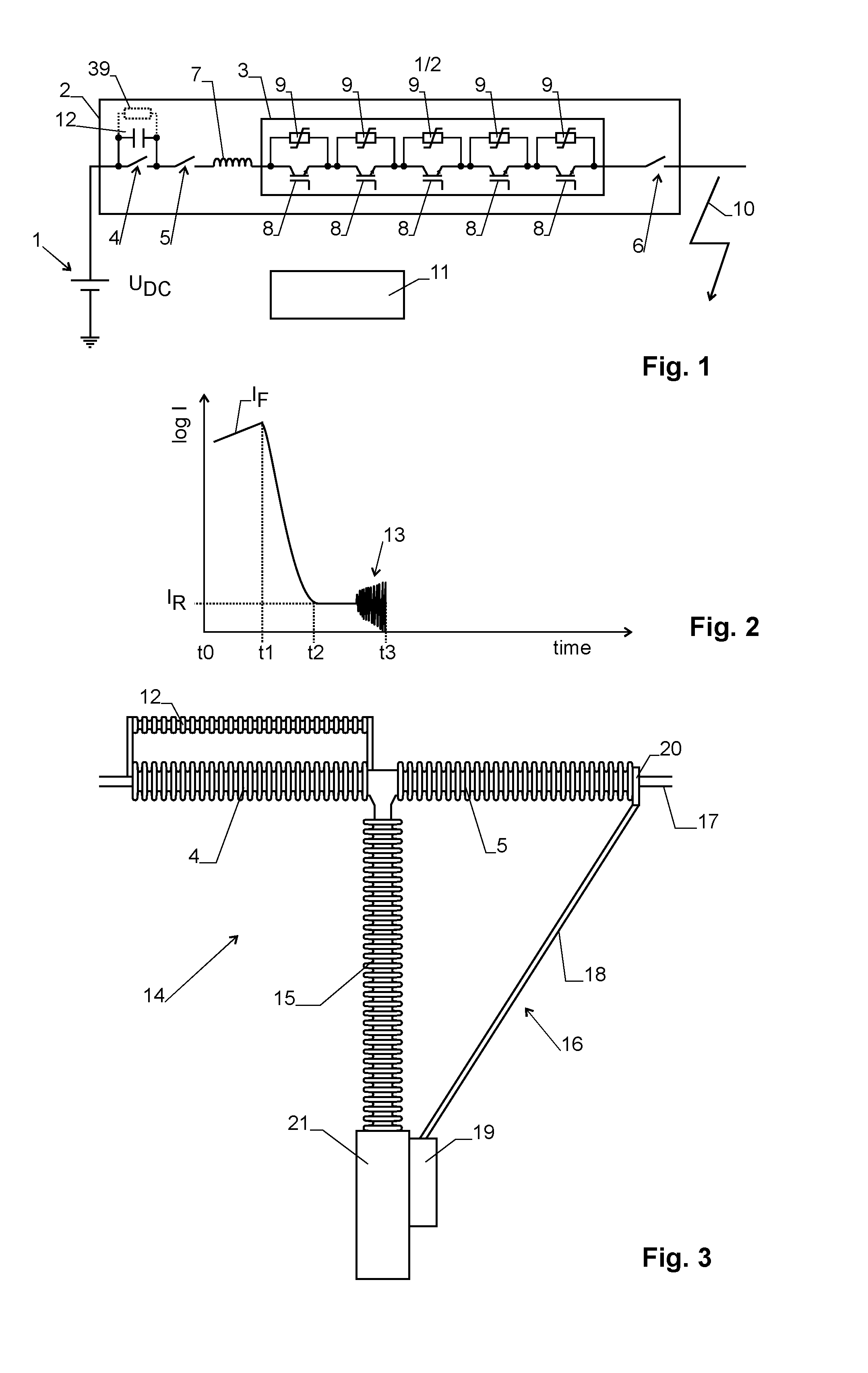
[0016]Exemplary embodiments of the present disclosure provide a method for switching off a high-voltage DC current from a voltage source delivering a nominal voltage by means of a circuit breaker, which includes a semiconductor switching assembly and at least one mechanical switch in series. The semiconductor switching assembly includes a plurality of semiconductor switches and a plurality of arresters in parallel to the semiconductor switches. Exemplary embodiments of the present disclosure also provide such a circuit breaker.

[0017]Accordingly, the circuit breaker used for interrupting a high-voltage DC current having a nominal voltage UDC, for example, a nominal DC voltage UDC, includes a semiconductor switching assembly and at least one mechanical switch in series. The semiconductor switching assembly includes a pluralit...


PUM


Abstract

A high voltage DC circuit breaker includes a semiconductor switching assembly in series with a mechanical switch. When the semiconductor switching assembly is switched off due to a current fault, a residual current flowing through arresters of the semiconductor switching assembly is switched off by the mechanical switch. A capacitor arranged parallel to the mechanical switch leads to passive resonance effects, which in turn induce current zero crossings in its arc. The current zero crossings allow for reliable extinguishing of the arc. The mechanical switch can be an AC circuit breaker.

Description

RELATED APPLICATIONS[0001]This application claims priority as a continuation application under 35 U.S.C. §120 to PCT / EP2011 / 072959, which was filed as an International Application on Dec. 15, 2011 designating the U.S., and which claims priority to European Application 10196908.7 filed in Europe on Dec. 23, 2010. The entire contents of these applications are hereby incorporated by reference in their entireties.FIELD[0002]The present disclosure relates to a method and a circuit breaker for switching off high-voltage DC currents using semiconductor switches as well as mechanical switches. The present disclosure also relates to a switching unit for breaking a high-voltage DC current and to a method for switching off a high-voltage DC current by means of the switching unit.BACKGROUND INFORMATION[0003]Interruption of direct currents (DC) is one of the major challenges for the realization of multi-terminal DC networks (MTDC). Several approaches have been investigated. For such a system, sp...

Claims


Application Information

Patent Timeline
Patent Type & Authority Applications(United States)
IPC IPC(8): H02H3/02
CPCH02H3/02H01H9/548H01H33/125H01H33/596H01H2009/543H02H3/025H02H3/087
Inventor OHLSSON, DANIELPANOUSIS, EMMANOUILHAFNER, JURGENBUJOTZEK, MARKUSSKARBY, PER
Owner HITACHI ENERGY SWITZERLAND AG
Why Eureka
Try Eureka