
Elastic wave filter

a filter and elastic wave technology, applied in the direction of impedence networks, electrical devices, etc., can solve the problems of leakage of elastic waves and difficulty in shifting impedances, and achieve the effect of suppressing spurious responses and suppressing reflection of diffracted elastic waves

Active Publication Date: 2013-10-24
NDK SAW DEVICES CO LTD
View PDF3 Cites 5 Cited by
  • Summary
  • Abstract
  • Description
  • Claims
  • Application Information

AI Technical Summary

Benefits of technology

The elastic wave filter described in this patent reduces the reflection of elastic waves and spurious responses in the frequency pass-band. It includes inclined electrode portions, a dummy electrode, and a busbar. The dummy electrode is placed between the electrode fingers and another busbar to suppress the reflection of diffracted elastic waves by the busbar and to prevent spurious response at the end portion of the filter. The dummy electrode has a width and pitch determined to prevent any period from being satisfied. These technical effects improve the performance and reliability of the elastic wave filter.

Problems solved by technology

This causes leakage of the elastic wave due to the diffraction of the elastic wave.
This causes spurious response at an edge of the frequency pass-band.
Accordingly, shifting the impedance is also becoming difficult.

Method used


Image

  • Elastic wave filter
  • Elastic wave filter
  • Elastic wave filter

Examples


Embodiment Construction

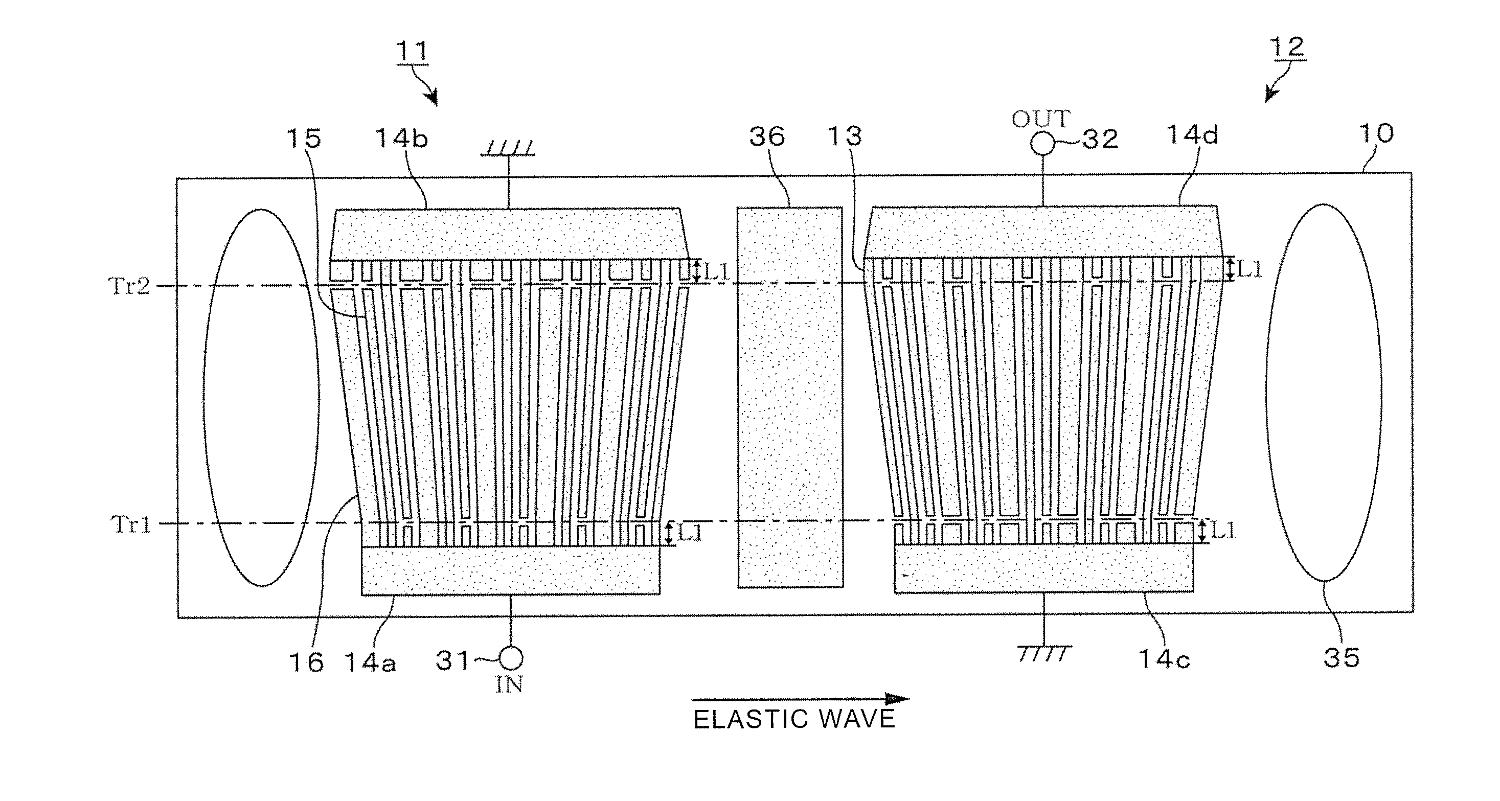
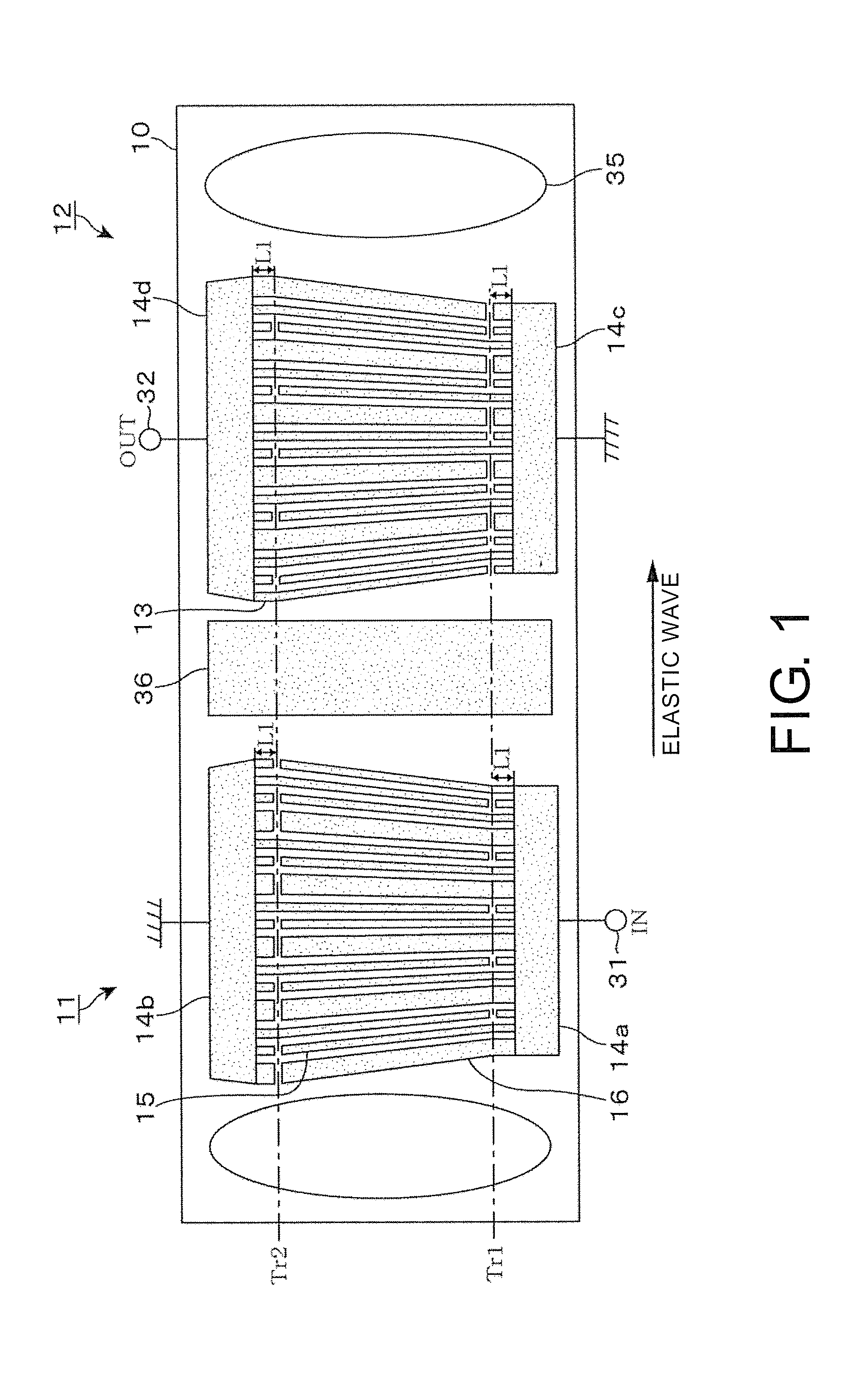
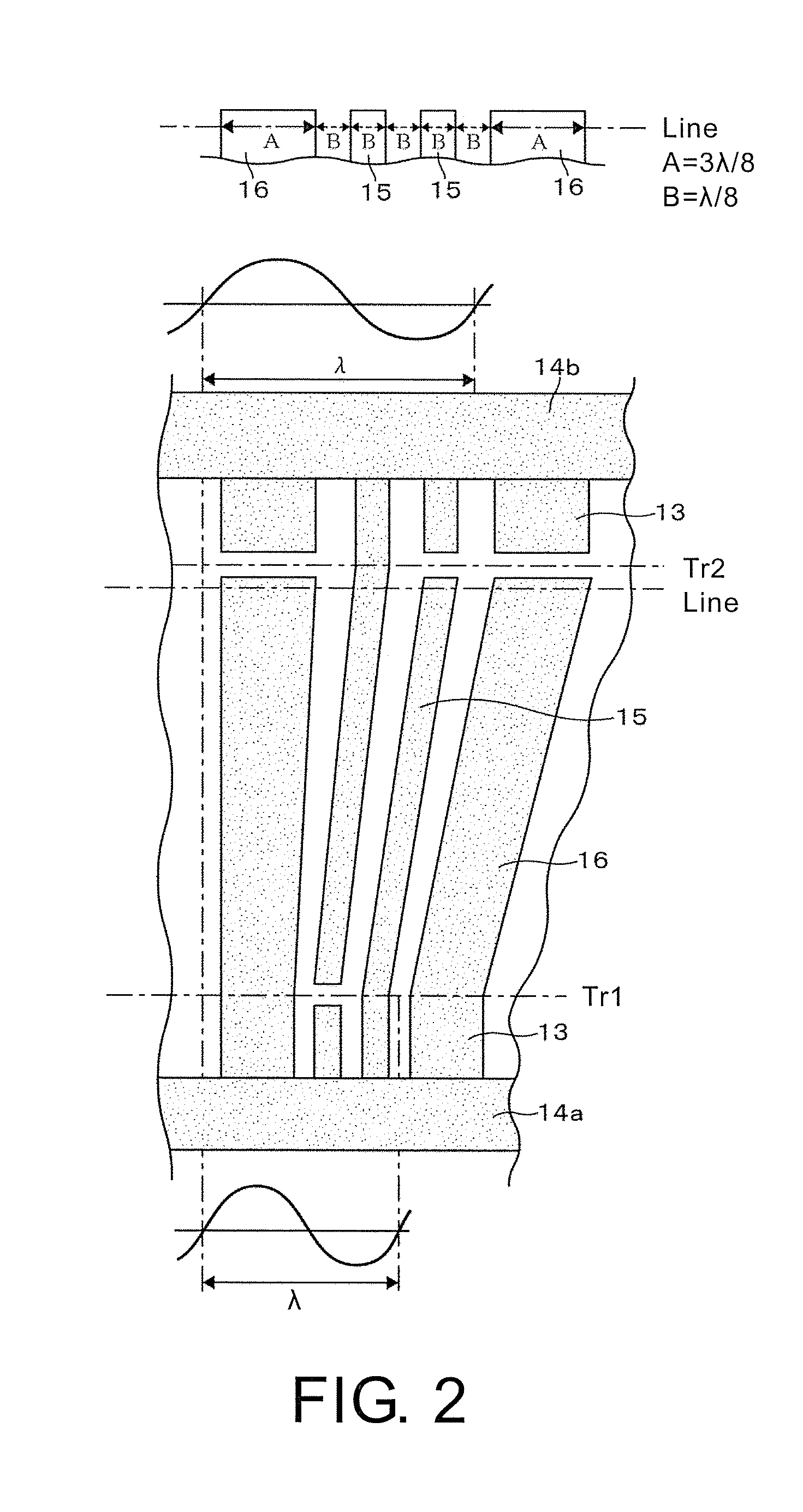
[0023]A description will be given of an elastic wave filter according to an embodiment of this disclosure by referring to FIG. 1 and FIG. 2. The elastic wave filter of this disclosure includes an input-side IDT electrode portion 11 and an output-side IDT electrode portion 12, and is formed on a piezoelectric substrate 10 such as LiNbO3 (lithium niobate). These IDT electrode portions 11 and 12 are disposed at a distance along a propagation direction of an elastic wave. Between the IDT electrode portions 11 and 12, a square shield electrode 36 connected to the ground potential is arranged. This elastic wave filter is formed by photolithography as follows. For example, a metal film such as aluminum is formed over the entire surface of the piezoelectric substrate 10. Subsequently, regions other than the above-describe electrodes are etched through a mask layer that is laminated on this metal film. Here, in the drawing, a sound absorbing material (damper) 35 is illustrated. The damper 35...


PUM


Abstract

An elastic wave filter includes electrode fingers, a first busbar and a second busbar, and inclined electrode portions each having a narrower distance between the electrode fingers from the first busbar toward the second busbar. The elastic wave filter includes a dummy electrode disposed in at least one of the input-side IDT electrode portion and the output-side IDT electrode portion to suppress reflection of a diffracted elastic wave by the busbar and to suppress spurious response at an end portion in a frequency pass-band. The dummy electrode has a width dimension and a pitch that are determined such that none of a period shorter than a shortest period of the electrode fingers and a period longer than a longest period of the electrode fingers is satisfied.

Description

CROSS REFERENCE TO RELATED APPLICATIONS[0001]This application claims the priority benefit of Japan application serial no. 2012-094878, filed on Apr. 18, 2012. The entirety of the above-mentioned patent application is hereby incorporated by reference herein and made a part of this specification.TECHNICAL FIELD[0002]This disclosure relates to an elastic wave filter such as a surface acoustic wave (SAW) filter.DESCRIPTION OF THE RELATED ART[0003]The SAW device uses a surface acoustic wave. In this SAW device, on a piezoelectric substrate, an electrode called an interdigital transducer (IDT) is arranged along a propagation direction of an elastic wave as an input-side electrode portion and an output-side electrode portion. The SAW device performs, between these two electrode portions, an electromechanical interconversion between an electrical signal and an elastic wave to provide a frequency selection (band-pass filter) characteristic. As one SAW device, a SAW filter is used as a band-p...

Claims


Application Information

Patent Timeline
IPC IPC(8): H03H9/64
CPCH03H9/64H03H9/14505H03H9/14558
Inventor TSUDA, TADAAKIOHTANI, TAKASHI
Owner NDK SAW DEVICES CO LTD
Learn More