Image forming apparatus and test image forming method

a technology of image forming apparatus and test image, which is applied in the direction of electrographic process apparatus, printing, instruments, etc., can solve the problems of deteriorating image quality, difficult to satisfactorily correct multiple exposures, and difficulty in reducing image density unevenness

Inactive Publication Date: 2013-10-24
CANON KK
View PDF6 Cites 7 Cited by
  • Summary
  • Abstract
  • Description
  • Claims
  • Application Information

AI Technical Summary

Benefits of technology

[0014]An embodiment of the present invention has been made to solve the problems described above, and it is an object of an embodiment of the present invention to provide an image forming apparatus capable of reducing density unevenness in an image formed by multiple exposures without fail.
[0015]It is another object of an embodiment of the present invention to provide a method of forming a test image suitable for the reduction of the density unevenness.
[0020]According to an embodiment of the present invention, fluctuations in the amount of light of each individual light emitting element or the like can be detected from a comparison between test images on a recording medium even in multiple exposures which use a plurality of light emitting elements. Density unevenness is thus reduced in an image formed by the image forming apparatus.

Problems solved by technology

This makes density unevenness more visible due to beam pitch deviations in the sub-scanning direction and an optical face angle error of the polygon mirror, thereby deteriorating image quality.
The resultant density unevenness in the image deteriorates the quality of the output image.
The technology of forming an image by the multiple exposures method, however, has the following problem.
It is therefore difficult in multiple exposures to satisfactorily correct density unevenness of an actual image by the conventional method in which only the densities of each test image that is formed with corresponding laser beam are referred to and are simply evened out.

Method used


Image

  • Image forming apparatus and test image forming method
  • Image forming apparatus and test image forming method
  • Image forming apparatus and test image forming method

Examples


first embodiment

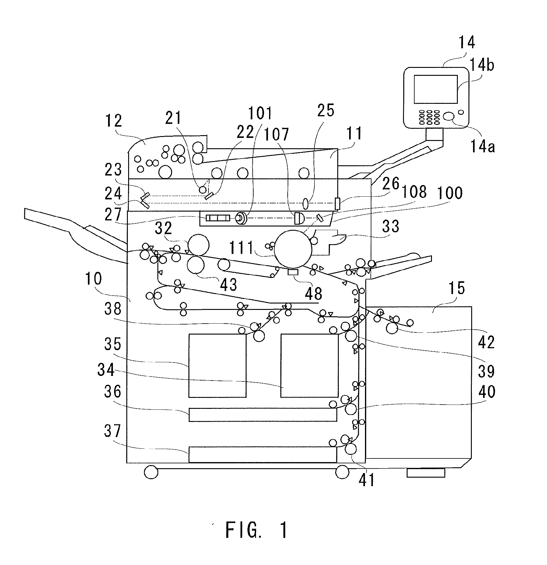
[0048]FIG. 1 is a structural diagram of an image forming apparatus according to a first embodiment of the present invention. This image forming apparatus includes a printer unit 10, which outputs an image of an original onto a recording medium such as recording paper, and a scanner unit 11, which reads data of the image of the original. An automatic original feeding mechanism 12 is provided on top of the scanner unit 11.

[0049]The image forming apparatus is operated by a user by setting a copy mode, a laser light amount adjustment mode, or the like via an operation unit 14. An operation button 14a is an input interface for operating the image forming apparatus. A display unit 14b of the operation unit 14 is capable of displaying various set values and current job status of the image forming apparatus. The display unit 14b is a touch panel and can handle, for example, an input of various types of data through touch operation on a display surface of the display unit 14b. The display un...

second embodiment

[0084]A second embodiment of the present invention is described next. In the second embodiment, test images are formed by single exposure that uses each laser beam separately (sub-test images) at the same time as the test image of the first embodiment which is formed by multiple exposures. This embodiment allows not only comparison among test images formed by multiple exposures but also comparison among test images formed by single exposure that uses each laser beam separately (sub-test images). Therefore, by uniformizing the amount of light in multiple exposures and simultaneously reducing the light amount difference among laser beams based on a comparison in the amount of light between lasers, the difference in lifetime among laser beams due to the difference in the amount of light of the laser beams can be reduced.

[0085]FIG. 13 is a diagram illustrating an example of a test image according to this embodiment in which images formed by single exposure that uses each laser beam sepa...


PUM


Abstract

Density unevenness is suppressed even in an image that is formed by a multiple exposures method in which the same region on a photoreceptor is exposed multiple times with different laser light sources (light emitting elements), by adjusting the amounts of light of the respective lasers based on a density difference among test images. An image is formed for each group of light emitting elements grouped together for multiple exposures by dividing, in the main scanning direction, the region of a test image formed on a recording medium. The images formed for the respective multiple-exposure light emitting element groups are compared to one another in density, to thereby adjust the amounts of light of the respective laser light sources (light emitting elements) and reduce fluctuations in image density.

Description

BACKGROUND OF THE INVENTION[0001]1. Field of the Invention[0002]The present disclosure relates to an image forming apparatus for performing image forming processing by electrophotography.[0003]2. Description of the Related Art[0004]Laser beam printers, digital copiers, and other similar types of image forming apparatus are equipped with an optical scanning device. The optical scanning device forms an electrostatic latent image on a photoreceptor by, for example, reflecting laser light that is emitted from a laser diode on a polygon mirror that is rotating at a constant speed.[0005]Optical scanning devices of recent years deal with printing speed enhancement and image resolution enhancement by multi-beam scanning technology in which a photoreceptor is scanned with a plurality of laser beams to form an image. This type of technology, which involves an increased number of laser beams, can enhance speed and resolution without raising the rotational speed of the polygon mirror or raising...

Claims


Application Information

Patent Timeline
Patent Type & Authority Applications(United States)
IPC IPC(8): B41J2/435
CPCG03G15/55G03G15/043
Inventor HIRANO, MASAYUKI
Owner CANON KK
Why Eureka
Try Eureka