Imaging apparatus

a technology of imaging apparatus and anti-shake, which is applied in the field of imaging apparatus, can solve the problems of increasing the cost of image sensor anti-shake, difficult to secure sufficient space for imaging sensor anti-shake, and limited slimming of imaging units, and achieves the effect of reducing the thickness of imaging units

Active Publication Date: 2013-10-24
HOYA CORP
View PDF4 Cites 148 Cited by
  • Summary
  • Abstract
  • Description
  • Claims
  • Application Information

AI Technical Summary

Benefits of technology

[0009]The present invention has been devised in view of the above mentioned drawbacks and provides an imaging apparatus which can carry out image-shake correction (image stabilization) while achieving miniaturization of the imaging apparatus, especially reduction in thickness thereof.

Problems solved by technology

The first type of anti-shake system tends to become complicated in structure and tends to increase in cost because a circuit board connected to the image sensor is moved so as to follow movements of the image sensor, which requires electrical components around the image sensor also to be movable components in addition to the image sensor.
In addition, the periphery of the imaging surface of the image sensor is required to be dust tight; however, in small imaging units intended for being incorporated into a mobile phone or a personal digital assistant, it is difficult to secure sufficient space for allowing the image sensor to perform an anti-shake (image shake correction / image-stabilizing) operation while maintaining the dust-tight structure of the image sensor.
The second type of anti-shake system has a structure such that the moving direction of the lens group, disposed behind the reflector, during an anti-shake operation corresponds to the direction of the thickness of the imaging unit (i.e., the forward / rearward direction of the imaging unit, wherein the direction toward an object to be photographed refers to the forward (front) direction of the imaging unit), and hence, there is a problem with providing enough space to house such an anti-shake structure in a slimmed-down imaging unit.
In other words, the slimming of the imaging unit is limited if this type of anti-shake system is used.
There is a similar problem also in the type of anti-shake system in which an image sensor is moved, instead of a lens group, in the direction of the thickness of the imaging unit.

Method used


Image

  • Imaging apparatus
  • Imaging apparatus
  • Imaging apparatus

Examples


Embodiment Construction

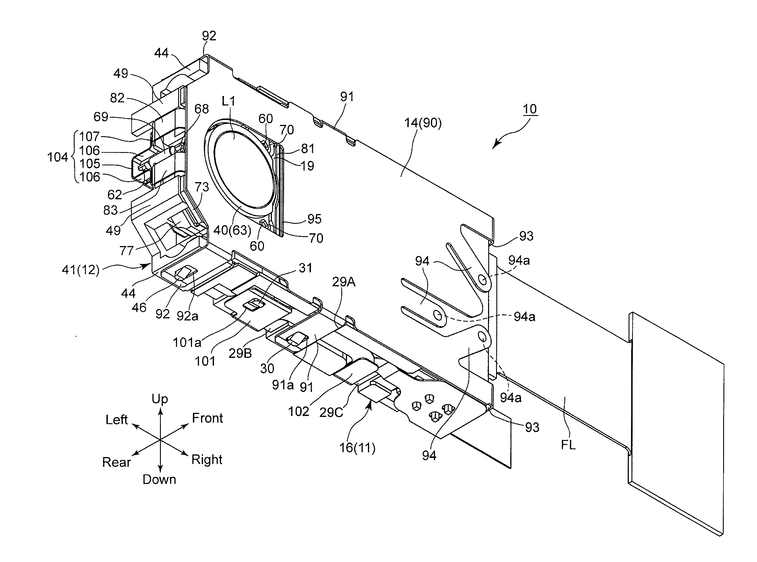
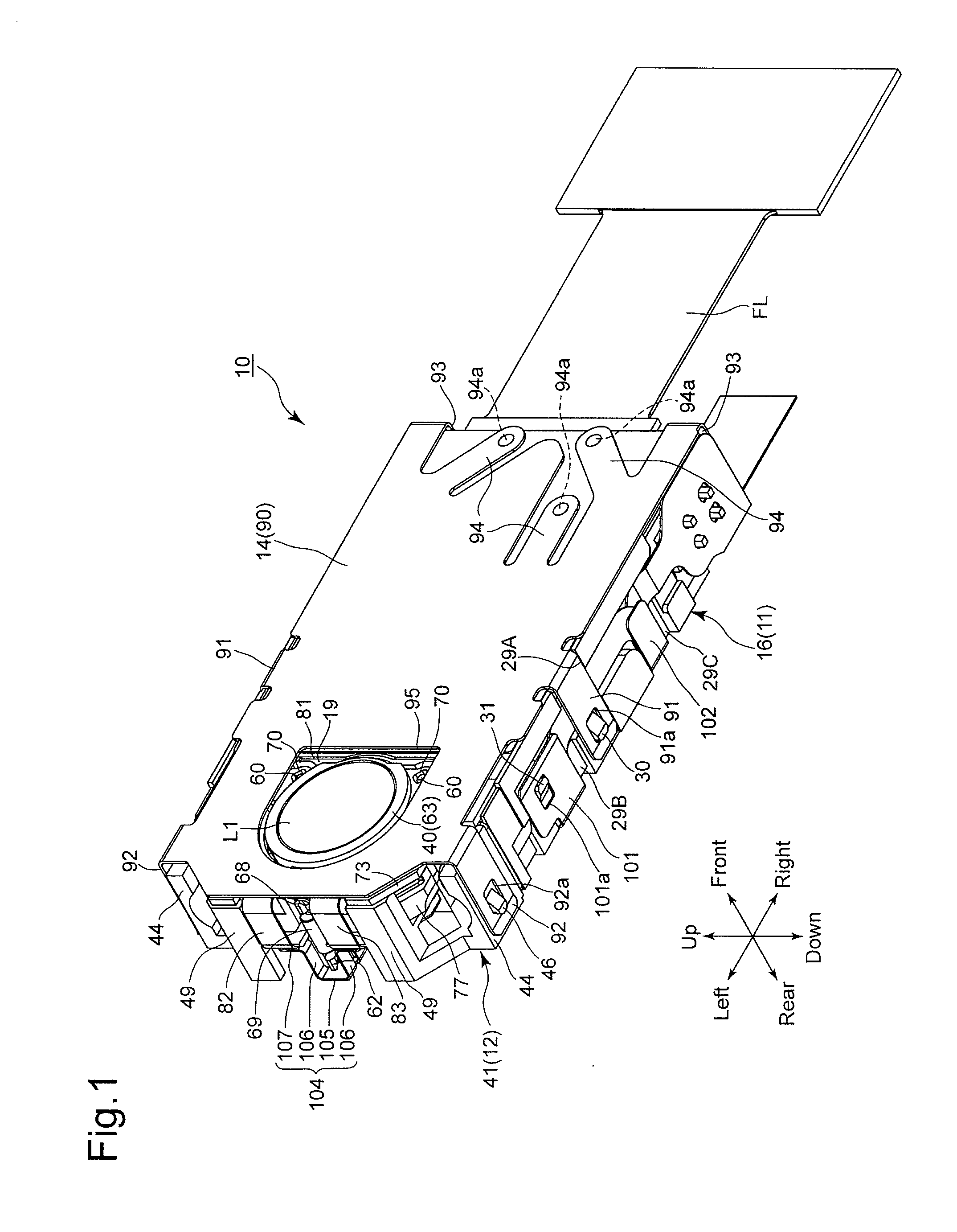
[0042]An embodiment of an imaging unit (imaging apparatus) 10 according to the present invention will be discussed below with reference to FIGS. 1 through 8. In the following descriptions, forward and rearward directions, leftward and rightward directions, and upward and downward directions are determined with reference to the directions of the double-headed arrows shown in the drawings. The object side corresponds to the front side. As shown by the outward appearance of the imaging unit 10 in FIGS. 1 and 4, the imaging unit 10 has a laterally elongated shape which is slim in the forward / rearward direction and long in the leftward / rightward direction.

[0043]As shown in FIGS. 6 and 8, the imaging unit 10 is provided with a first lens group (front lens group) G1, a second lens group (movable lens group) G2 and a third lens group (movable lens group) G3. The first lens group G1 is provided with a first prism (reflector) L11 and the imaging unit 10 is provided with a second prism (second...


PUM


Abstract

An imaging apparatus includes a front lens group, which constitutes part of an imaging optical system, at a fixed position with respect to an optical axis direction, wherein the front lens group includes a front lens element and a reflector and the reflector reflects light rays exiting from the front lens element; a movable lens group provided closer to the image plane side than the front lens group and movable along the optical axis; a support member which supports the reflector; a movable frame which supports the front lens element and is supported by the support member to be movable along a plane orthogonal to the optical axis of the front lens element; and a driver which drives the movable frame in the plane, in accordance with vibrations applied to the photographing optical system, to reduce image shake.

Description

BACKGROUND OF THE INVENTION[0001]1. Field of the Invention[0002]The present invention relates to an imaging apparatus equipped with an anti-shake (image shake correction / image stabilizing) system.[0003]2. Description of the Related Art[0004]In recent years, mobile electronic devices which are designed mainly for taking still / moving photographic images, such as digital cameras (still-video cameras) and digital camcorders (motion-video cameras), and other mobile electronic devices which are designed to be capable of taking such photographic images as a subsidiary function, such as mobile phones equipped with a camera and personal digital assistants (PDAs) equipped with a camera, have become widespread. In these types of mobile electronic devices, it is common to provide the mobile electronic device therein with an imaging unit (imaging apparatus) which is configured so that an image sensor (image pickup device) and a photographing optical system, for guiding light emanating from a pho...

Claims


Application Information

Patent Timeline
Patent Type & Authority Applications(United States)
IPC IPC(8): H04N5/232G02B27/64
CPCH04N5/23287G02B27/646G02B7/102G02B13/0065G02B13/009G03B5/02G03B17/17G03B2205/0015G02B15/143507H04N23/55H04N23/60G03B5/06G03B30/00H04N23/687G02B7/023
Inventor NOMURA, HIROSHINAKAMURA, TOSHIKI
Owner HOYA CORP
Why Eureka
Try Eureka