
Freestanding Thin Film For A System For Neural Applications

a neural application and freestanding technology, applied in the field of thin films, can solve the problems of substantial thin film length, increased length of cable wiring, and increased length of winding, and achieve good protection

Active Publication Date: 2013-10-24
MEDTRONIC BAKKEN RES CENT
View PDF2 Cites 46 Cited by
  • Summary
  • Abstract
  • Description
  • Claims
  • Application Information

AI Technical Summary

Benefits of technology

This patent describes a method for manufacturing thin films that exceed the length of the carrier wafer without the need for folding. The method allows for the use of wider range of materials and stacks. The thin films can be deposited on a flat surface with several thin films arranged in parallel. A spiral design is used to wind the thin films around a lead core, which allows for a smooth surface and good protection of the thin film. A groove can be provided for the thin film to make sure it is protected and does not form a corrugation on the outer surface of the lead. The method also enables the manufacturing of multiple thin films or electrodes on one wafer, reducing costs and ensuring identical thin films for better production and lead manufacturing.

Problems solved by technology

Magnetic resonance (MR) safety of these implantable devices is an important issue.
However, the winding substantially increases the length of the cable wiring.
In the case of a DBS lead that is manufactured with winded thin film, the length of the thin film is substantial and can exceed the size of the carrier substrate.
However, a MR safe DBS system will need a thin film of several tens of centimeters.
Folding the film severely compromises the mechanical properties of the thin film.
Meanwhile the folding strains the materials at the inside of the curvature and can cause the materials in the thin film to crack, break and buckle.
Moreover, the manufacturing process of leads, the winding of the thin film around a core, is more complicated.
The discontinuity of the thin film folding disrupts the winding process of the film around a core.

Method used


Image

  • Freestanding Thin Film For A System For Neural Applications
  • Freestanding Thin Film For A System For Neural Applications
  • Freestanding Thin Film For A System For Neural Applications

Examples


Embodiment Construction

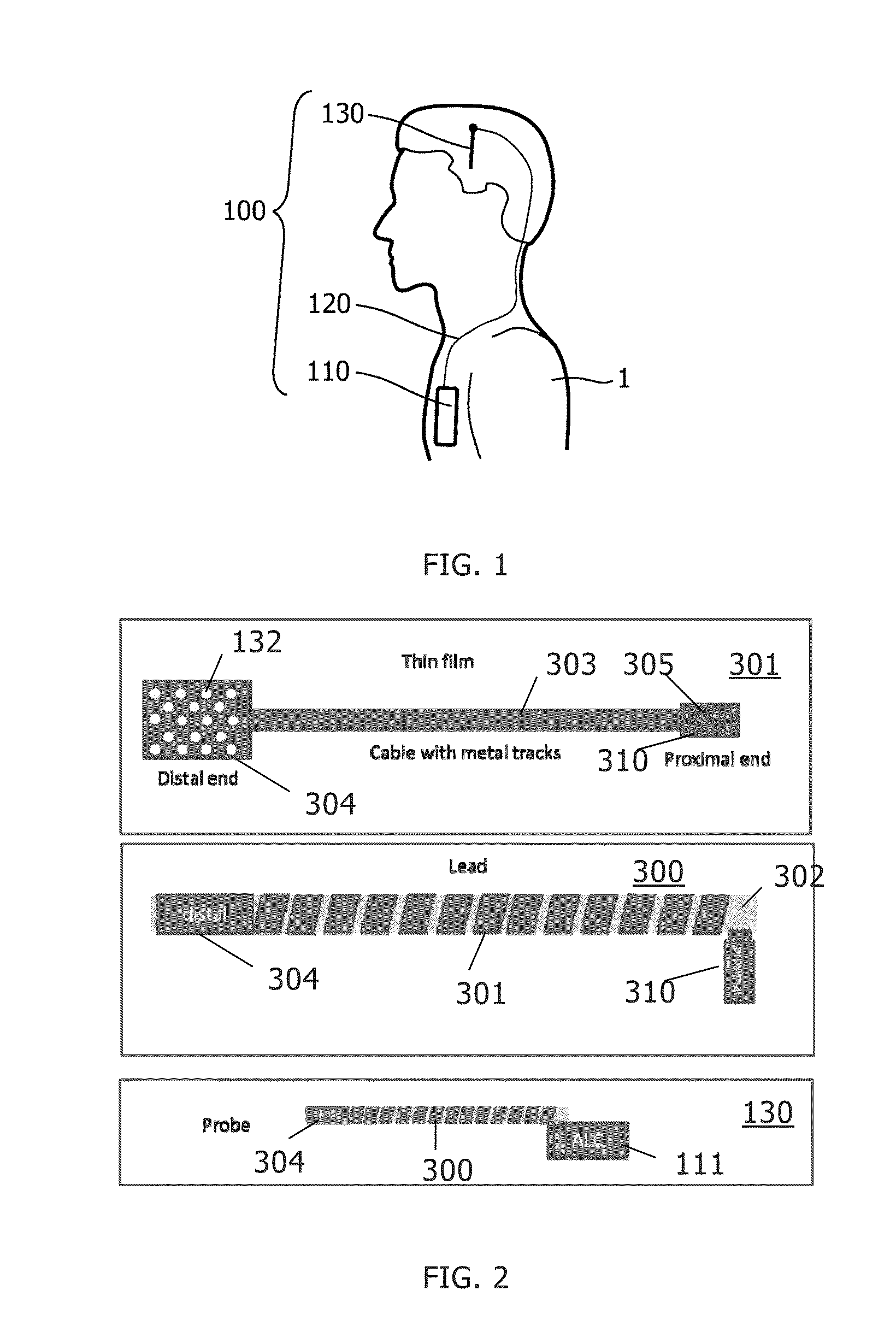
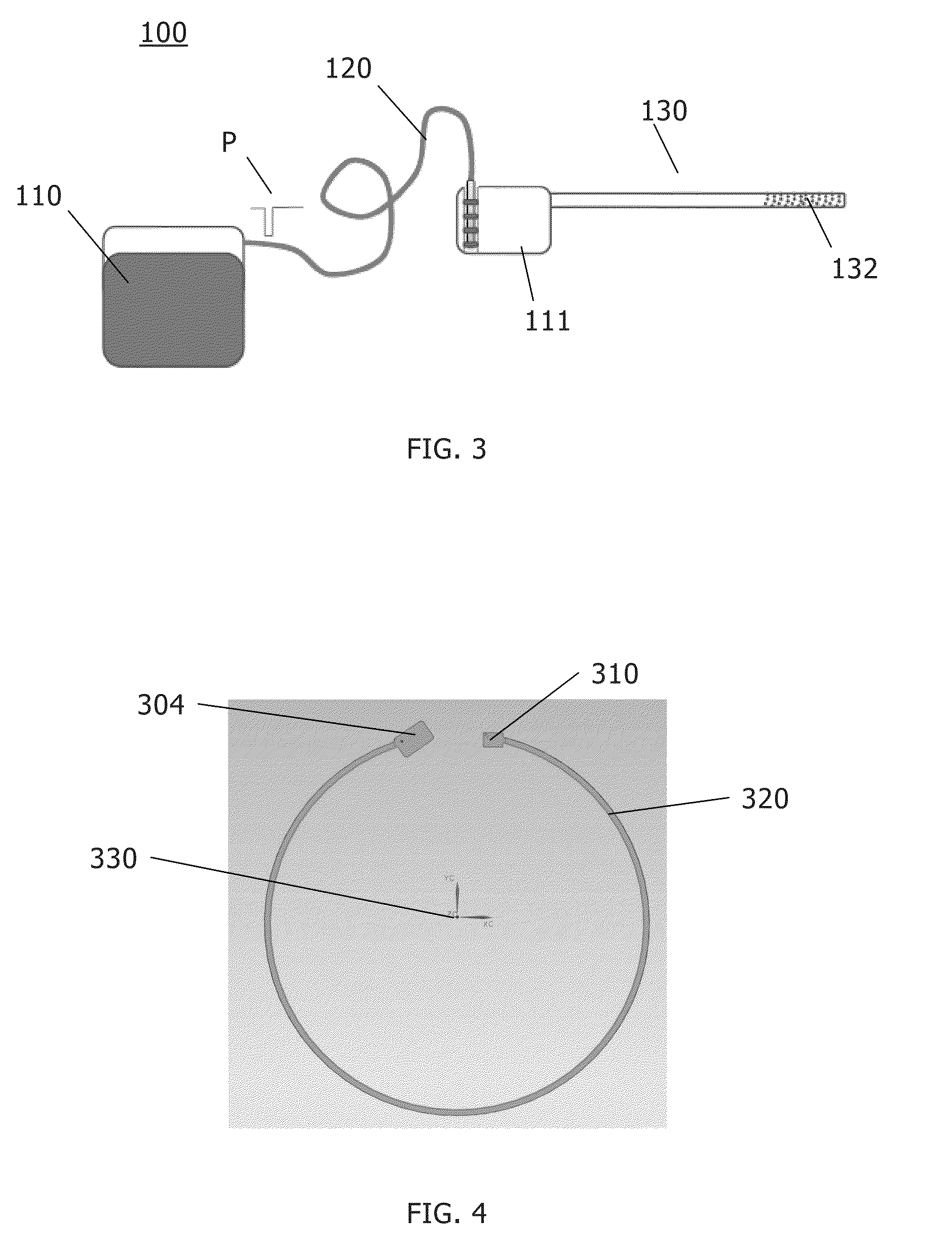
[0045]A possible embodiment of a neurostimulation system 100 for deep brain stimulation (DBS) is shown in FIG. 1. The neurostimulation system 100 comprises at least a controller 110 that may be surgically implanted in the chest region of a patient 1, typically below the clavicle or in the abdominal region of a patient 1. The controller 110 can be adapted to supply the necessary voltage pulses. The typical DBS system 100 may further include an extension wire 120 connected to the controller 110 and running subcutaneously to the skull, preferably along the neck, where it terminates in a connector. A DBS lead arrangement 130 may be implanted in the brain tissue, e.g. through a burr-hole in the skull.

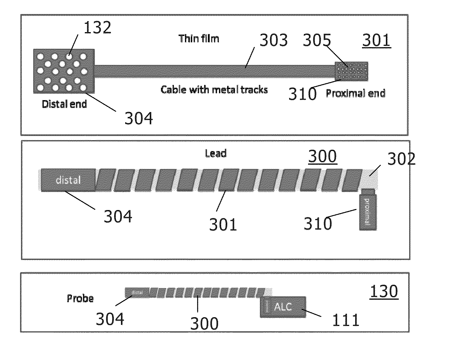
[0046]FIG. 2 further illustrates a typical architecture for a Deep Brain Stimulation probe 130 that comprises a DBS lead 300 and an Advanced Lead Connector (ALC) element 111 comprising electronic means to address electrodes 132 on the distal end 304 of the DBS lead 300. The lead 300 comprise...


PUM


Abstract

A lead for use in neural stimulation comprises a core section having a proximal end and a distal end. A plurality of electrodes is coupled to the core section proximate the distal end. At least one contact is coupled to the core section proximate the proximal end. At least one thin film is wound around the core section from the proximal end to the distal end and electrically coupling the at least one contact and the plurality of electrodes. The at least one thin film forms a curved substantially planar shape in a relaxed state before being wound around the core section.

Description

CROSS-REFERENCE TO RELATED APPLICATIONS[0001]This application claims the benefit of EP 12 164 860 and U.S. Provisional Patent Application No. 61 / 636,177 both filed Apr. 20, 2012, entitled “A freestanding thin film, especially a freestanding thin film for a system for neural applications”, and incorporated by reference herein in their entirety.BACKGROUND OF THE INVENTION[0002]The present invention generally relates to thin films, and in some embodiments, thin films for a system for neural applications, methods of manufacturing of thin films, wafers, lead cores for a lead, leads, probes and systems for neural applications. Implantable neurostimulation devices have been used for the past ten and more years to treat acute or chronic neurological conditions. Deep brain stimulation (DBS), the mild electrical stimulation of sub-cortical structures, belongs to this category of implantable devices, and has been shown to be therapeutically effective for Parkinson's disease, Dystonia, and Trem...

Claims


Application Information

Patent Timeline
Patent Type & Authority Applications(United States)
IPC IPC(8): A61N1/05
CPCA61N1/0551A61N1/0529A61N1/0534A61N1/36125A61N1/086H05K1/00
Inventor DECRE, MICHEL MARCEL JOSEYOUNG, EDWARD WILLEM ALBERTDECKERS, JACOBUS ADRIANUS JOHANNA MARIAVAN PIJKEREN, DIRKWANG, KEHENNEKEN, VINCENT ADRIANUS
Owner MEDTRONIC BAKKEN RES CENT
Learn More