Exhaust gas purification system and method for controlling the same

a technology of exhaust gas purification system and injection valve, which is applied in the direction of engines, mechanical equipment, machines/engines, etc., can solve the problems of reducing the efficiency of exhaust gas purification, the reducing agent injection valve the aqueous solution filling the reducing agent supply apparatus may not be completely collected into the storage tank, so as to prevent the clogging of the reducing agent injection valve due to the possibility of solidification, the likelihood of solid

Active Publication Date: 2013-10-31
BOSCH CORP
View PDF5 Cites 23 Cited by
  • Summary
  • Abstract
  • Description
  • Claims
  • Application Information

AI Technical Summary

Benefits of technology

[0010]Furthermore, in configuring the invention, the condition satisfaction determination section preferably determines whether or not the urea aqueous solution is likely to be solidified when detecting that the ignition switch is turned off, based on at least one of the temperature, temperature gradient and outside-air temperature of the reducing agent injection valve. Whether or not the urea aqueous solution in the reducing agent injection valve is likely to be solidified depends on the temperature of the reducing agent injection valve, so the determination based on the temperature, temperature gradient and outside-air temperature of the reducing agent injection valve allows more accurate estimation of the likelihood of solidification of the urea aqueous solution.
[0011]Furthermore, another aspect of the invention is a method for controlling an exhaust gas purification system, the system including: a DPF for collecting exhaust particles contained in exhaust gas; a reducing agent injection valve for injecting urea aqueous solution as a reducing age

Problems solved by technology

However, the exhaust gas purification system described in JP-A-2009-215891 has a problem that, in the process of heating and then cooling urea aqueous solution in the reducing agent injection valve after the internal-combustion engine is stopped, the urea aqueous solution may be solidified to interfere with the supply of urea aqueous solution when the internal-combustion engine is started, thereby decreasing the exhaust gas purification efficiency.
Specifically, in the exhaust gas purification system, when the internal-combustion engine is stopped, purge process of collecting urea aqueous solution filling the reducing agent supply apparatus into the storage tank is generally performed, but the urea aqueous solution filling the reducing agent supply apparatus may not be completely collected into the storage tank due to the structure of

Method used


Image

  • Exhaust gas purification system and method for controlling the same
  • Exhaust gas purification system and method for controlling the same
  • Exhaust gas purification system and method for controlling the same

Examples


first embodiment

[0027]1. Exhaust Gas Purification System

[0028](1) Overall Configuration

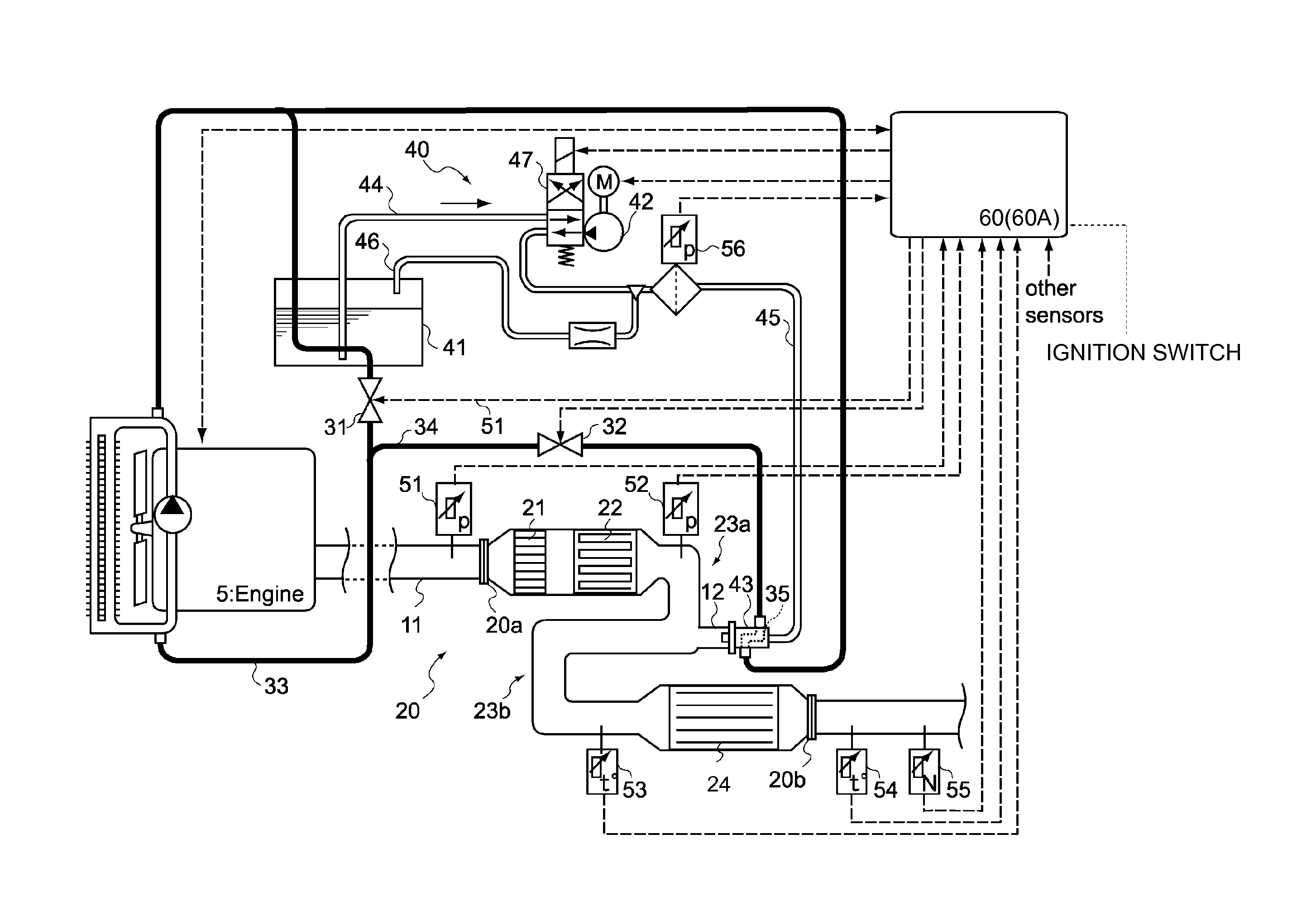
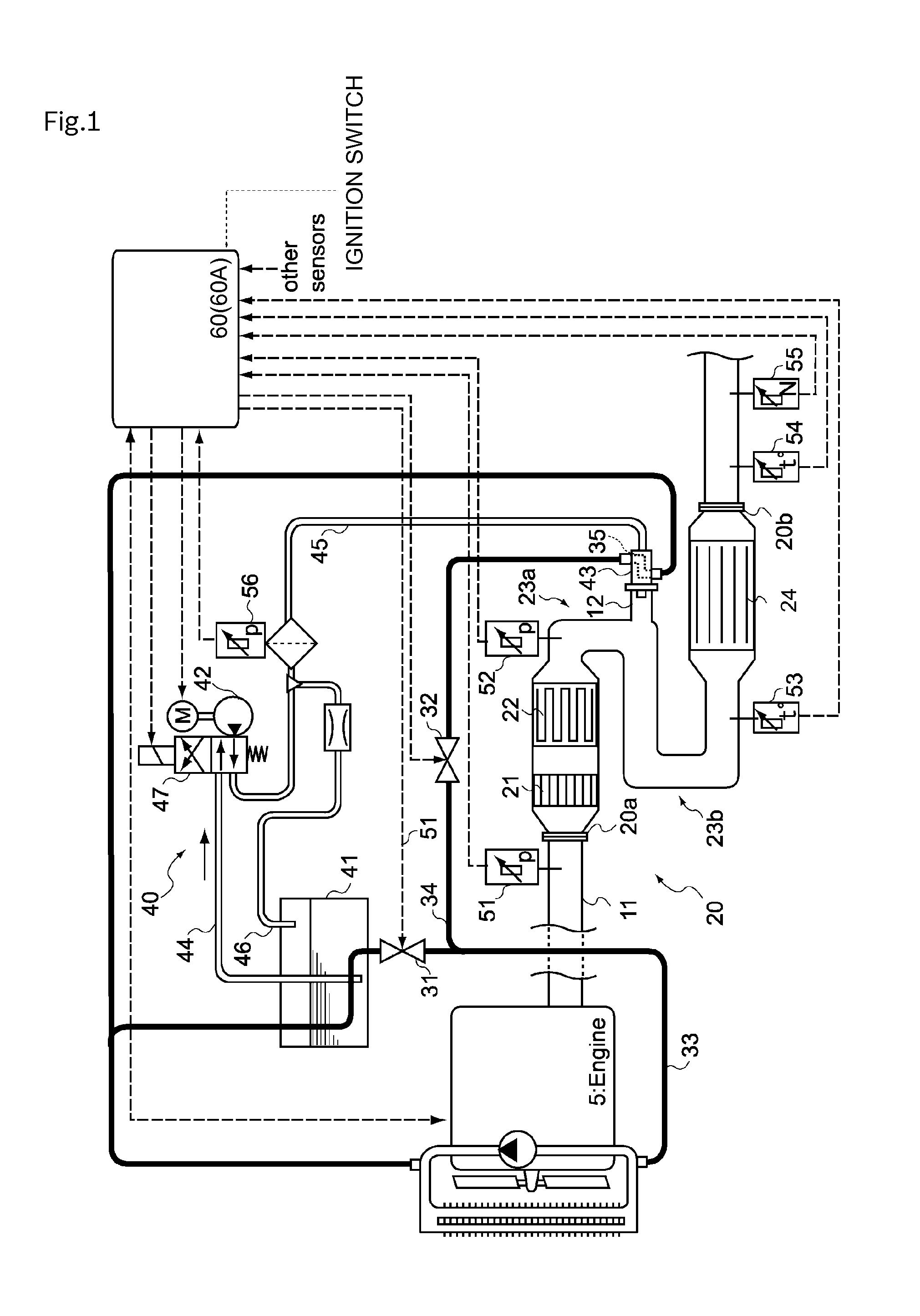
[0029]FIG. 1 shows an overall configuration of an exhaust gas purification system (hereinafter may be simply referred to as “system”) 10 in accordance with a first embodiment of the invention. The system 10 includes as main components: an exhaust gas purification unit 20 having a DPF 22 and an SCR catalyst 24; a reducing agent supply apparatus 40 including a reducing agent injection valve 43; and a control unit 60 for performing forced regeneration control of the DPF22 and operation control of the reducing agent supply apparatus 40. The system 10 is an apparatus configured so that the DPF 22 collects PM contained in exhaust gas and urea aqueous solution as a reducing agent is used to selectively purify NOx contained in exhaust gas in the SCR catalyst 24.

[0030](2) Exhaust Gas Purification Unit

[0031]The exhaust gas purification unit 20 includes an oxidation catalyst 21, the DPF 22 and the SCR catalyst 24 in this or...

second embodiment

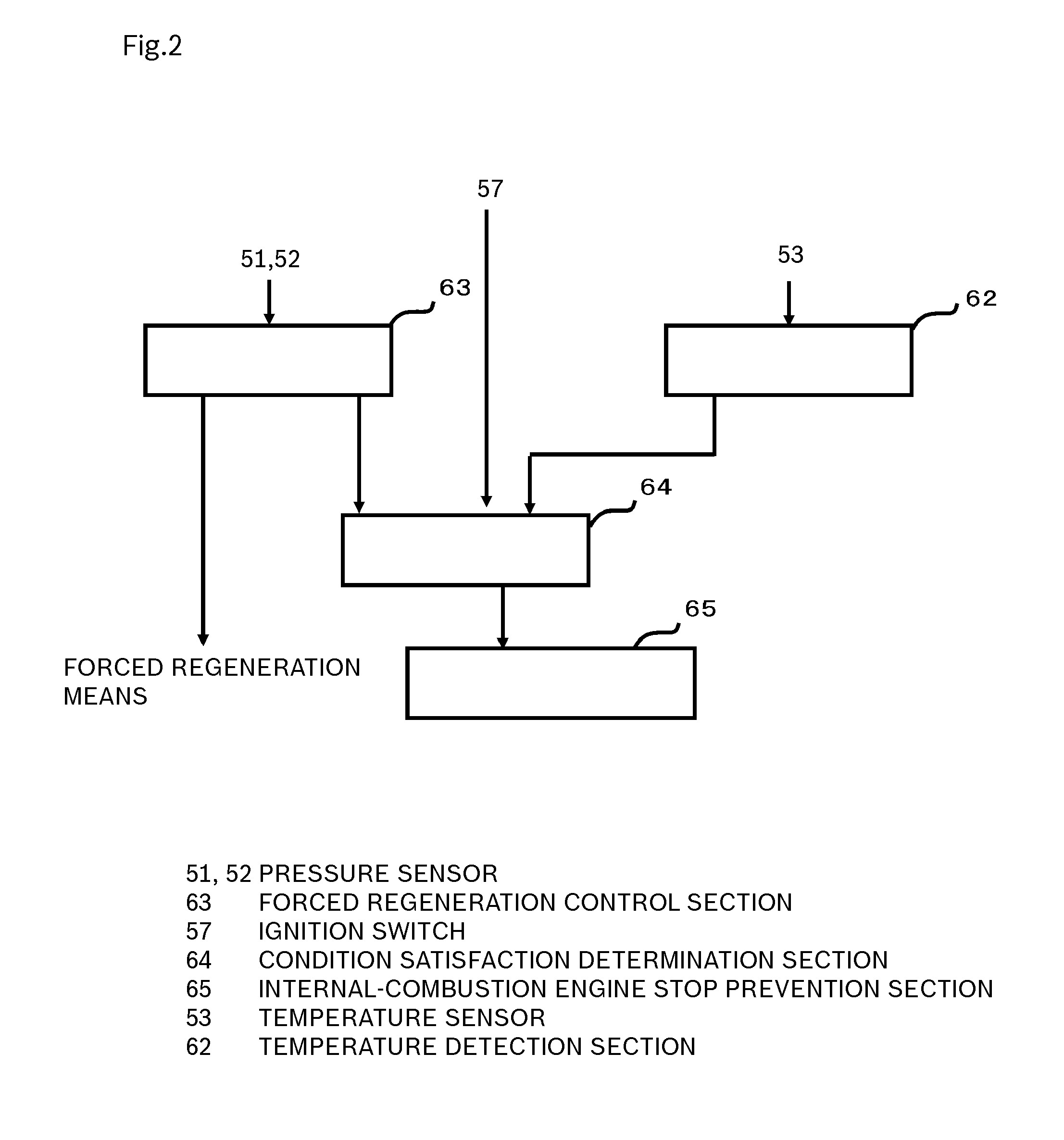
[0072]According to an exhaust gas purification system and a method for controlling the same in accordance with a second embodiment of the invention, when the internal-combustion engine is stopped or when it is assumed that the internal-combustion engine is stopped while the internal-combustion engine is operating, if it is determined that urea aqueous solution is likely to be solidified, an operator of the internal-combustion engine is prompted to restart the internal-combustion engine or not to stop the internal-combustion engine.

[0073]The exhaust gas purification system in accordance with this embodiment basically has a configuration similar to that of the exhaust gas purification system in accordance with the first embodiment (see FIG. 1), but its control unit provides a function and control contents different from that of the exhaust gas purification system in accordance with the first embodiment. Then, with reference to FIG. 1 and FIGS. 8-13, the control unit included in the ex...


PUM


Abstract

[Problem] To provide an exhaust gas purification system capable of preventing clogging of a reducing agent injection valve due to solidified urea aqueous solution to prevent decrease in the exhaust gas purification efficiency of an internal-combustion engine.
[Means for Resolution] An exhaust gas purification system including a DPF, a reducing agent injection valve and an SCR catalyst in this order from the exhaust upstream side includes: a condition satisfaction determination section for determining whether or not urea aqueous solution is likely to be solidified when detecting that an ignition switch is turned off; and an internal-combustion engine stop prevention section for preventing the internal-combustion engine from being stopped, based on a determination by the condition satisfaction determination section.

Description

BACKGROUND OF THE INVENTION[0001]The present invention relates to an exhaust gas purification system and a method for controlling the same. More particularly, the invention relates to an exhaust gas purification system and a method for controlling the same capable of eliminating clogging of a reducing agent injection valve due to solidified urea aqueous solution.[0002]Conventionally, exhaust gas of an internal-combustion engine included in a vehicle contains nitrogen oxides (hereinafter referred to as “NOx”) and particulate matter (hereinafter referred to as “PM”). Among them, NOx can be reduced to purify exhaust gas using, for example, a urea SCR system. The urea SCR system includes: a reducing agent supply apparatus for pumping urea aqueous solution as a reducing agent from a storage tank by a pump and supplying the urea aqueous solution from a reducing agent injection valve into an exhaust pipe; and SCR catalyst, a type of exhaust gas purification catalyst capable of adsorbing am...

Claims


Application Information

Patent Timeline
IPC IPC(8): F01N3/10
CPCF01N3/208F01N2430/00F01N2610/105F01N2900/1616Y02T10/24F01N3/10F01N3/2066F01N11/00Y02T10/12
Inventor WATANABE, MASANORIMIYAMOTO, TAKESHIKUROGI, FUMIYASU
Owner BOSCH CORP
Why Eureka
Try Eureka