Circulating Fluidized Bed Boiler Having Two External Heat Exchangers for Hot Solids Flow

Active Publication Date: 2013-10-31
AMEC FOSTER WHEELER ENERGIA
View PDF4 Cites 5 Cited by
  • Summary
  • Abstract
  • Description
  • Claims
  • Application Information

AI Technical Summary

Benefits of technology

[0015]An object of the present invention is to provide a circulating fluidized bed boiler, in which problems and drawbacks of the prior art discussed above are minimized.

Problems solved by technology

A problem the construction of the PCT publication solved related to the traditional location of the fluidized bed heat exchange chambers on the outside walls of the lower section of the furnace.
While the CFB boilers grew, it was not possible to increase the size of the fluidized bed heat exchange chambers accordingly, as increasing the height of a heat exchange chamber resulted in the increase of pressure losses in the fluidization air, and an increase in the width of the heat exchanger was not possible due to a lack of space.
When all the above-discussed and other considerations were taken into account in the design of the heat exchange arrangement, however, the construction of the arrangement became less optimal for some specific applications.
First, since the upper heat exchange chamber is supposed to discharge the cooled solids to the lower one, the channel between the heat exchange chambers runs between the upper heat exchange chamber and the furnace forcing positioning of the first / upper heat exchange chamber substantially far from the furnace wall. This also means that the solids separator has to be positioned far from the furnace, as the upper heat exchange chamber is normally positioned right below the separator, and supported from the separator.
Second, as the lower heat exchange chamber is supposed to be able to receive all the cooled solids from the upper heat exchange chamber, and possibly, also some additional solids from the internal circulation, it is clear that the volume of the lower heat exchange chamber should at least correspond to the one of the upper heat exchange chamber. As already discussed above in connection with the PCT publication (WO 2007 / 128883 A2), neither the height nor the width (in a direction parallel to the furnace wall) of the lower heat exchanger can be chosen freely, but both the pressure loss in the fluidization, and the space occupied by the heat exchange chamber have to be considered. The above consideration results in that the dimensions of the lower heat exchange chamber are substantially equal with the upper one. Thereby, there is very little room in connection with the lower section of the furnace for the equipment necessary for running the boiler, such as, for example, the start-up burner, a temperature measuring device for measuring the lower furnace temperature, a pressure measurement device for measuring the bed pressure, and feeds for introducing fuel, bed material, secondary air, additives, recirculated flue gas (if in use), etc.
Third, due to the various running alternatives, i.e., control options in the prior art boiler, there are conduits and channels for each alternative. For instance, the upper heat exchange chamber has one inlet from the separator, and several outlet channels and lift channels. One lift channel and outlet channel leading to the lower heat exchanger, another lift channel and outlet channel leading to the furnace, and overflow channels leading to both the lower heat exchange chamber and to the furnace. In addition to the channels, rather complicated fluidization means and controllers for adjusting the fluidizations are also required at the bottom of the upper heat exchange chamber. If, and when, the various channels and conduits require bellows to separate components in different temperatures, the bellows, again, occupy space, and also increase the costs of the heat exchanger arrangement together with the already numerous channels, conduits, fluidization equipment, and control systems that have been discussed above. And, still further, all of the channels and conduits need to be either made of water / steam tube walls and connected to the rest of the steam / water system, or made of a refractory material. Irrespective of the manufacture, this adds to the expenses as constructing the channels of water / steam tube walls or refractory material is a complicated and time-consuming task.

Method used


Image

  • Circulating Fluidized Bed Boiler Having Two External Heat Exchangers for Hot Solids Flow
  • Circulating Fluidized Bed Boiler Having Two External Heat Exchangers for Hot Solids Flow
  • Circulating Fluidized Bed Boiler Having Two External Heat Exchangers for Hot Solids Flow

Examples


Embodiment Construction

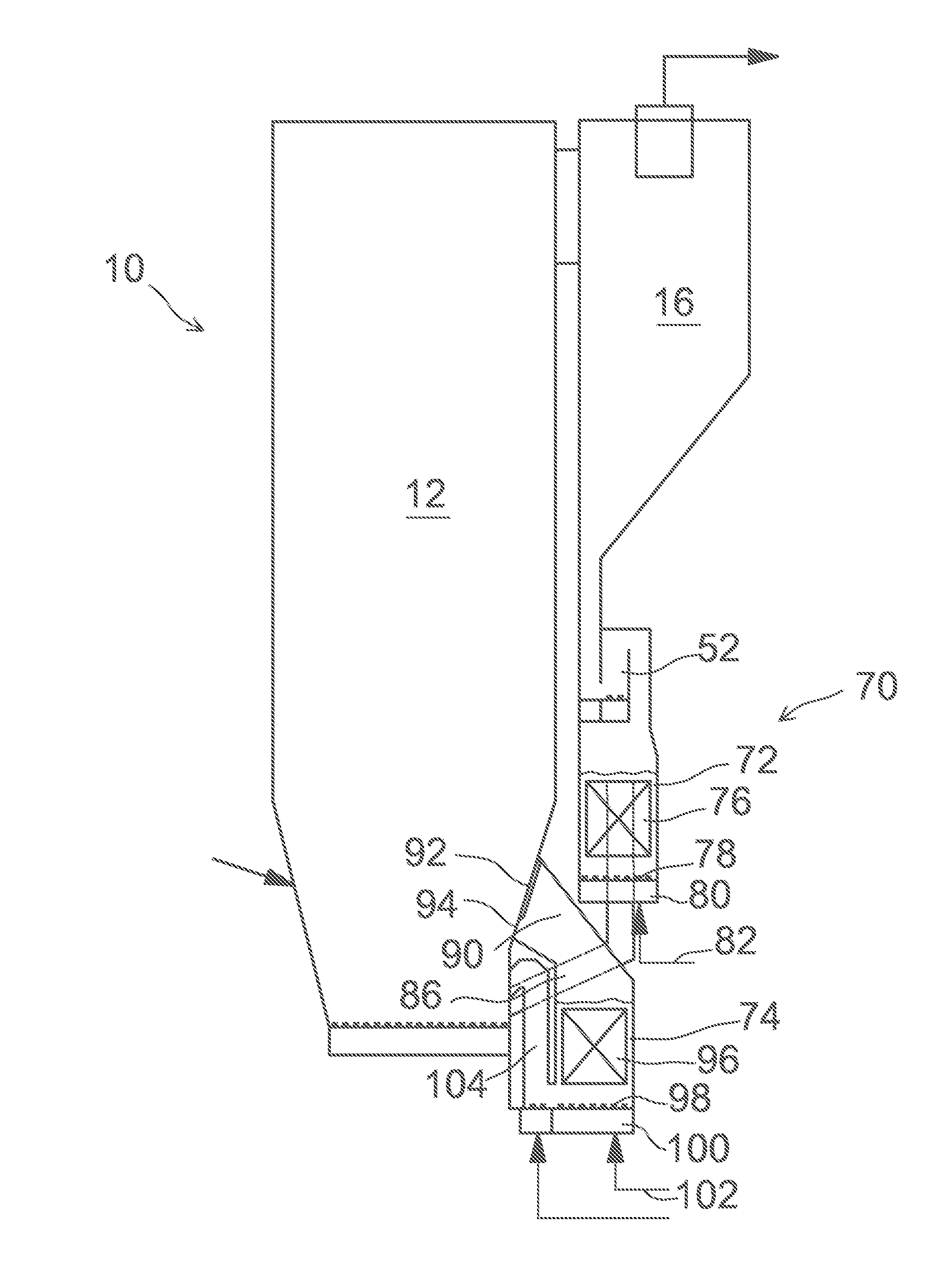
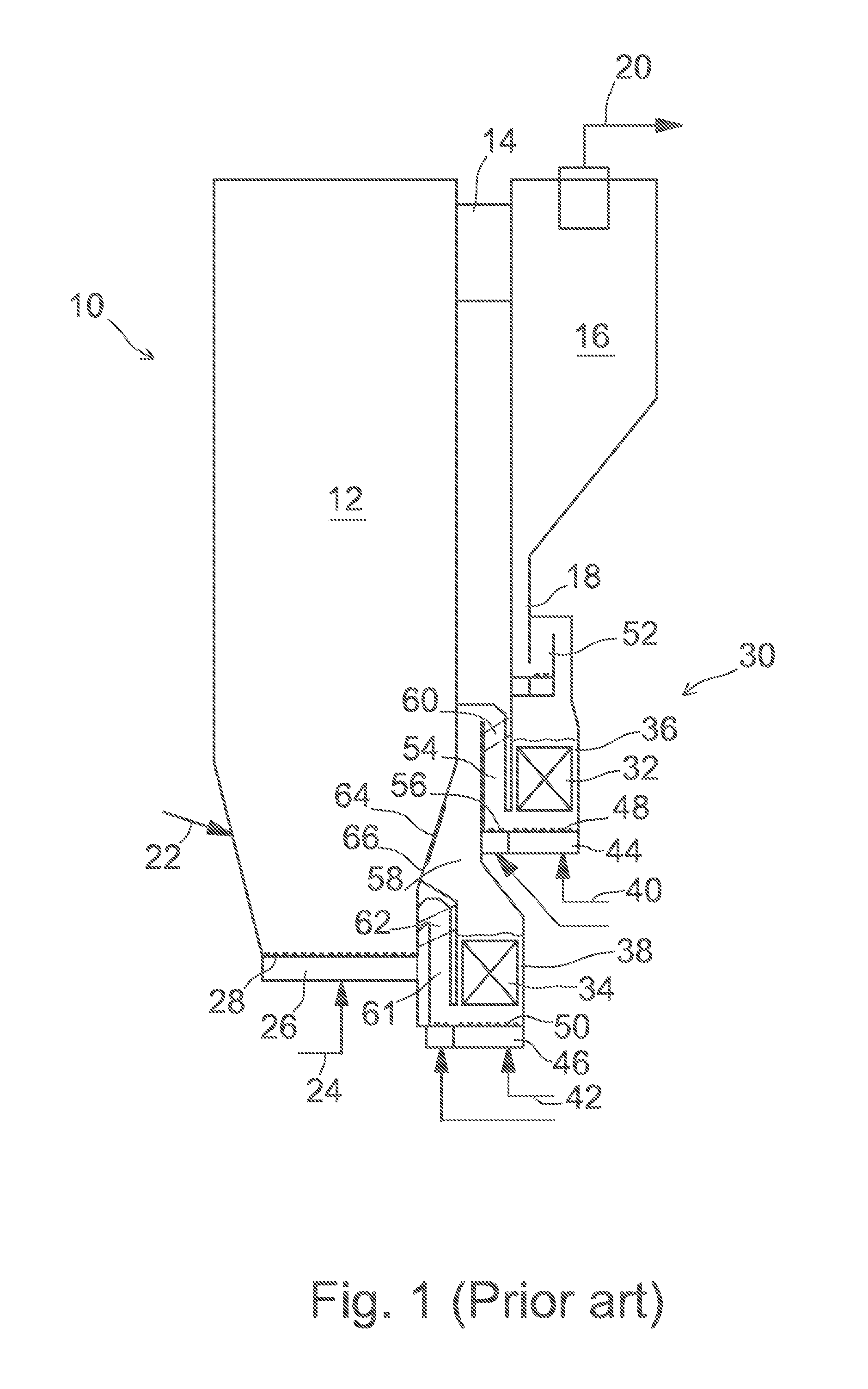
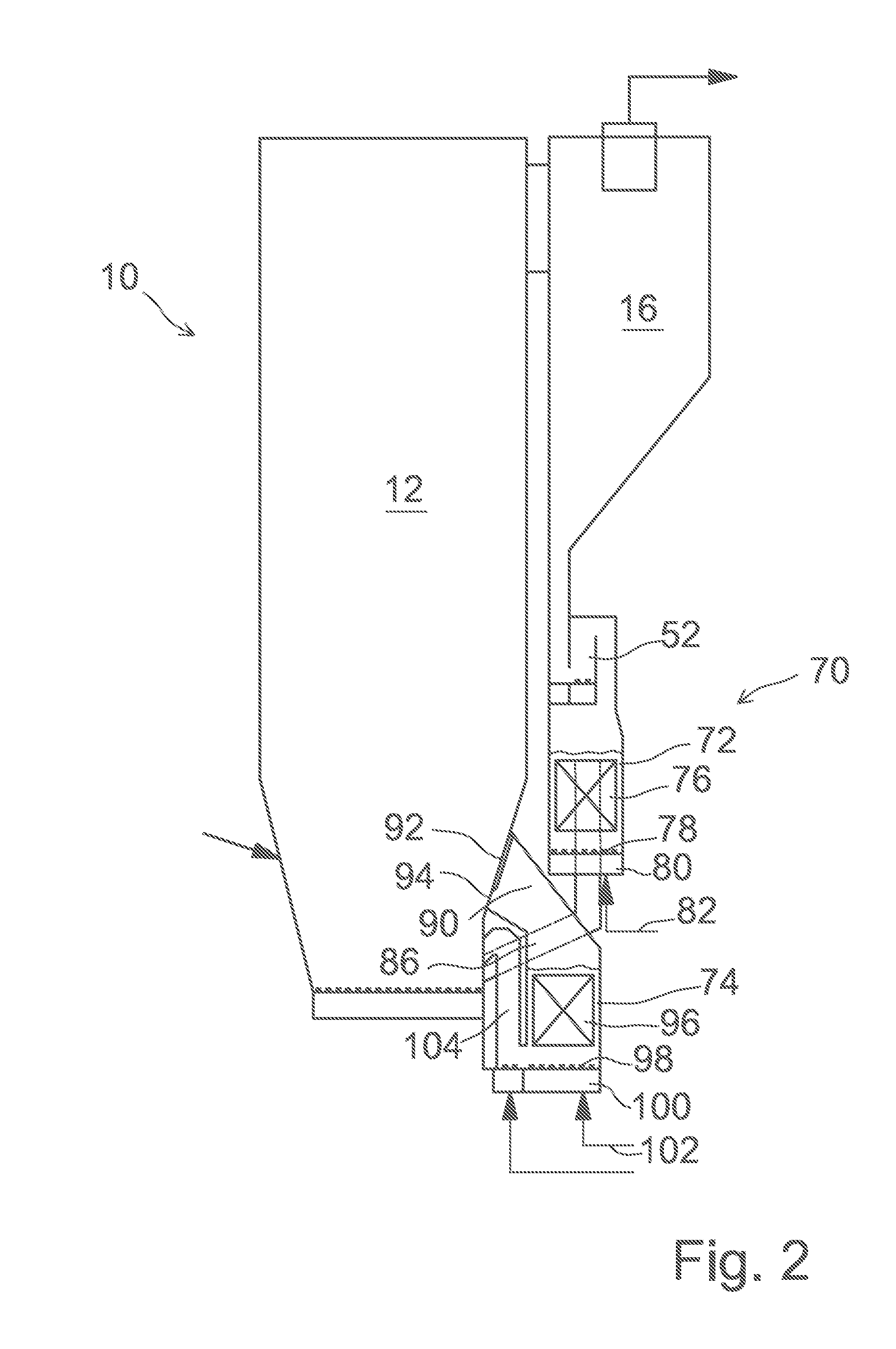
[0039]FIG. 1 illustrates a prior art circulating fluidized bed (CFB) boiler 10 comprising a furnace 12 for combusting fuel, an outlet channel 14 connected to the upper section of the furnace 12 for the discharge of flue gas out of the furnace 12, a solids separator 16 for receiving the flue gas via the outlet channel 14 from the furnace 12, and for separating solid particles from the flue gas. The CFB boiler 10 further comprises, at the lower portion of the solids separator 16, a return channel 18 for taking the hot solids separated by the solids separator 16 out of the separator 16 towards the lower section of the furnace 12, and, at the upper portion of the solids separator 16, a flue gas duct 20 for removing cleaned flue gas to the backpass of the boiler 10, gas cleaning devices, and further, through the stack to the environment. The outlet channel 14, the solids separator 16, and the return channel 18 form a so-called external hot circulation, where the hot solids entrained in t...


PUM


Abstract

A circulating fluidized bed boiler including a furnace for combusting solid carbonaceous fuel in a fast fluidized bed, the furnace having walls made of water/steam tube panels and used for evaporating water fed therein. A solids separator arranged adjacent to a sidewall of the furnace separates solids entrained with exhaust gas discharged via an outlet channel from an upper portion of the furnace. A gas seal conveys at least a portion of the separated solids to a first fluidized bed heat exchange changer arranged downstream of the gas seal and has internal heat exchange surfaces. A first lift channel has a lower end connected to a bottom portion of the first fluidized bed heat exchanger chamber and an upper end connected to an upper end of a first return channel for discharging solids from the first fluidized bed heat exchange chamber and for taking the cooled solids to a lower portion of the furnace. A second fluidized bed heat exchange chamber is arranged adjacent to a lower sidewall of the furnace and has internal heat exchange surfaces, an inlet channel arranged between the second fluidized bed heat exchange chamber and the furnace for introducing hot solids from the furnace to the second heat exchange chamber, a second lilt channel having a lower end connected to a bottom portion of the second fluidized bed heat exchange chamber and an upper end connected to discharge the solids to the lower portion of the furnace. The first fluidized bed heat exchanger chamber is positioned above the second.

Description

CLAIM OF PRIORITY[0001]This application is a U.S. national stage application of PCT International Application No. PCT / FI2012 / 050172, filed Feb. 22, 2012, published as International Publication No. WO 2012 / 113985 A1, and which claims priority from Finnish patent application number 20115181, filed Feb. 24, 2011.FIELD OF THE INVENTION[0002]Our invention relates to a circulating fluidized bed boiler. In more detail, the circulating fluidized bed boiler of the present invention is preferably a once through utility (OTU) boiler, for example, for power generation or industrial steam production. As the size of boilers increases, the relation of the wall surface area to the volume of the furnace usually becomes disadvantageous, which may cause problems, for example, in positioning of the different devices and conduits related to the furnace, as well as feed and mixing of different materials. The present invention especially relates to solving problems related to large circulating fluidized b...

Claims


Application Information

Patent Timeline
Patent Type & Authority Applications(United States)
IPC IPC(8): F22B31/00F22D1/02F23C10/04
CPCF22B31/003F23C10/04F22D1/02F22B31/0092F23C10/10F23C10/26F23C10/32F22B27/14F22B31/00
Inventor KAUPPINEN, KARIKINNUNEN, PERTTI
Owner AMEC FOSTER WHEELER ENERGIA
Why Eureka
Try Eureka