High-capacity/efficiency transmission line design

a transmission line, high-efficiency technology, applied in the direction of buildings, buildings, constructions, etc., can solve the problems of limited load-carrying ability, most limiting, and limited steady-state stability achieve the effects of improving the surge impedance load (sil) of the transmission line, improving the aesthetic profile, and improving the design and engineering simplicity

Active Publication Date: 2013-10-31
BOLD TRANSMISSION LLC
View PDF5 Cites 19 Cited by
  • Summary
  • Abstract
  • Description
  • Claims
  • Application Information

AI Technical Summary

Benefits of technology

[0010]In all embodiments of the invention, a high-capacity, high-efficiency 345 kV overhead transmission line design offers performance advantages relative to typical configurations now in use in the electric utility industry. This design provides a viable alternative to the use of series-compensated 345 kV lines and / or higher-voltage lines for transporting efficiently large power blocks over long distances (e.g., 100 miles); one that is superior in terms of simplicity of design and engineering, construction and operation, grid expandability, life expectancy, and life cycle cost.
[0011]The preferred embodiment of the invention represents double-circuit (and single-circuit / double-circuit-capable) lines, characterized by a compact interphase configuration using bundled conductors suspended from structures with a low, aesthetic profile. The new structure preferably is comprised of a single arch-shaped tubular steel crossarm supporting both circuits symmetrically about a single tubular steel pole shaft. Three phases with two, three, four (or more) bundled conductors each are preferably held together in a “delta” arrangement by means of V-string suspension insulator assemblies and interphase insulators, while maintaining desired phase-to-structure insulator assembly connections. This preferred embodiment of the invention improves the surge impedance loading (SIL) of a transmission line (i.e., a measure of line loadability), reduces its series impedance, lowers both resistive and corona (air ionization) losses, and moderates electromagnetic fields (EMF) and audible noise effects at the ground level—all achieved in a cost effective manner.

Problems solved by technology

It has been established through engineering analysis and practice that load-carrying ability, or loadability, of a transmission line is limited by one or more of the following factors: (i) thermal rating, (ii) voltage-drop constraint, and (iii) steady-state stability limitation.
Thermal rating is an outcome of the conductor and / or terminal equipment selection process, and is most limiting for lines shorter than 50 miles.
Longer lines are limited primarily by voltage-drop and / or stability considerations, both of which are directly affected by the length-dependent impedance of the line.
However, due to public opposition, multiple lower-voltage lines are built with series compensation to reduce the impedance and achieve the required loadability objectives.
These applications invariably are accompanied by concerns such as subsynchronous resonance (SSR) and subsynchronous control interactions (SSCI), known to pose risks to electrical machinery and grid stability.
Other concerns include system protection complexities, maintenance and spare equipment requirements, electrical losses, limited life expectancy relative to that of the line itself, and future grid expandability challenges.

Method used


Image

  • High-capacity/efficiency transmission line design
  • High-capacity/efficiency transmission line design
  • High-capacity/efficiency transmission line design

Examples


Embodiment Construction

)

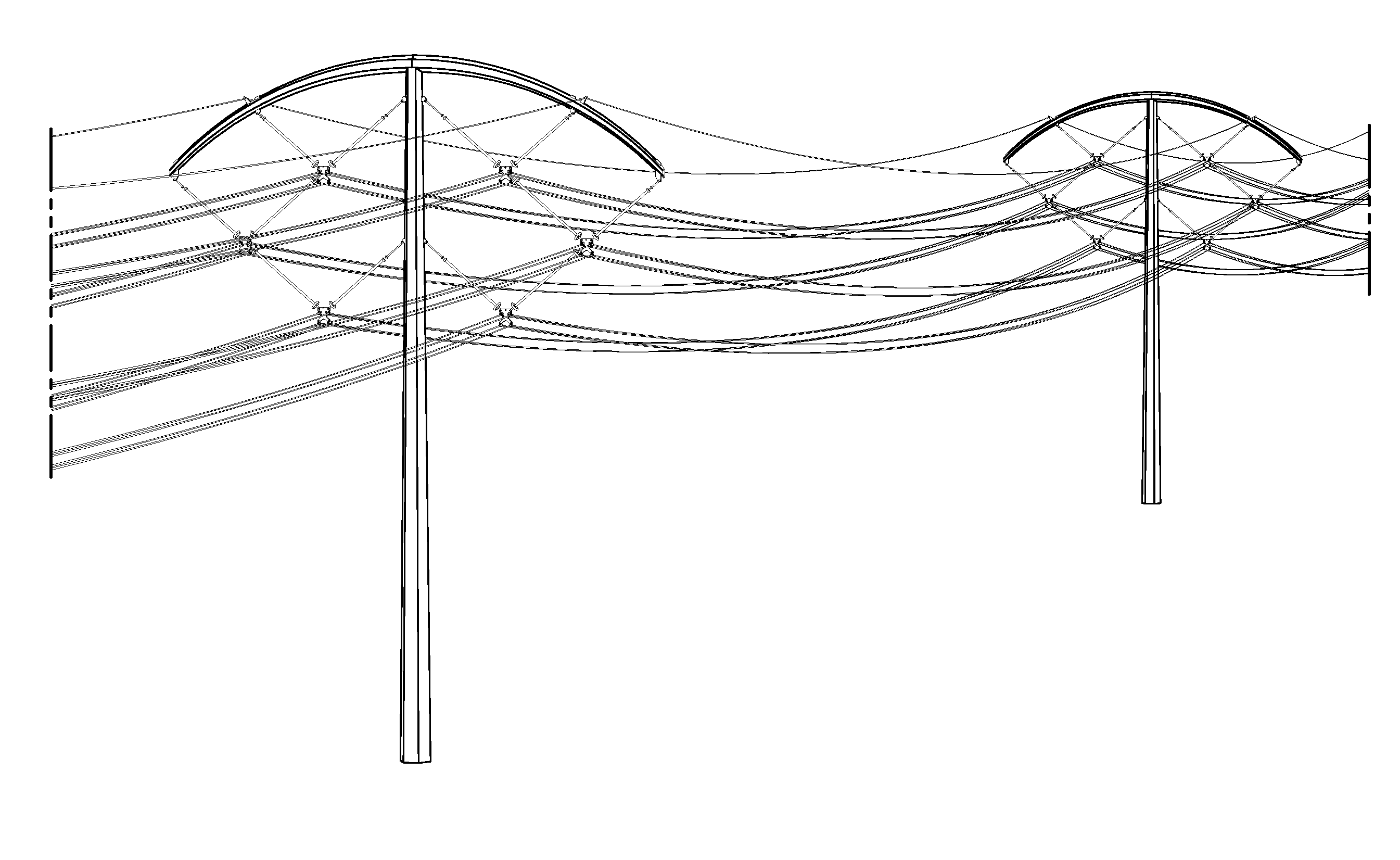
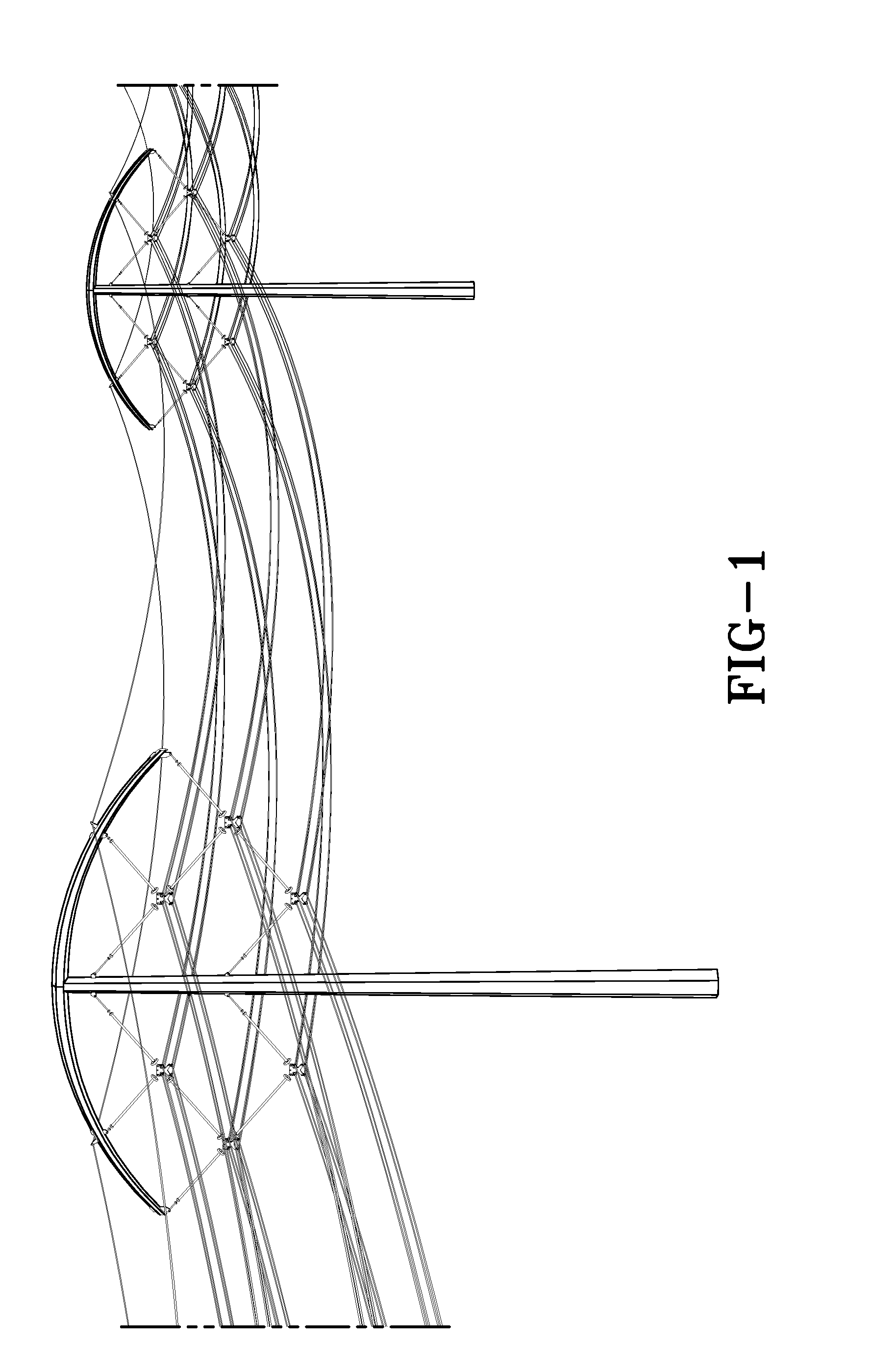
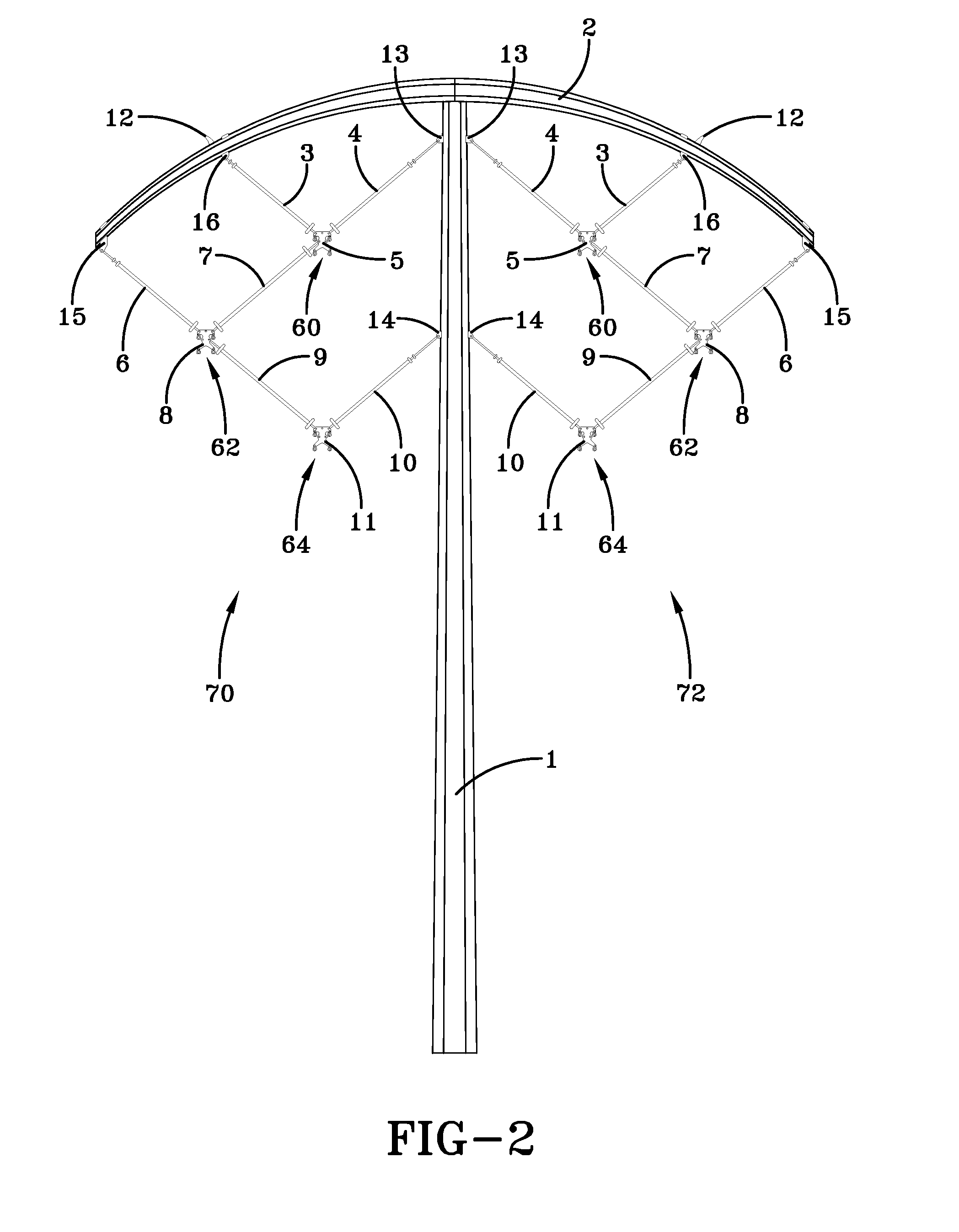
[0025]FIG. 1 shows the preferred embodiment of a 345 kV double-circuit line design of the present invention. It features a streamlined, relatively low-profile structure with phase-conductor bundles arranged into compact “delta” configurations by means of interphase insulators (“delta” means in a substantially triangular shape with internal angles in the range of 30 to 120 degrees). Compact delta configurations have the advantage of improved line surge impedance loading (SIL), lower series impedance, and reduced ground-level EMF effects (“compact” means a relatively closer arrangement than typical transmission line configurations that avoids the need for series compensation or any significant amount of series compensation; “compact” means in the range of 10 to 20 feet between any two phases). SIL, a loading level at which the line attains self-sufficiency in reactive power (i.e., no net reactive power into or out of the line), is a convenient “yardstick” for measuring relative loada...


PUM


Abstract

A transmission tower structure for suspending from an arched crossarm a three phased circuit arranged in a compact delta configuration that improves the surge impedance loading (SIL) of a transmission line, reduces its series impedance, lowers both resistive and corona losses, and moderates electromagnetic fields and audible noise effects at the ground level—all achieved in a cost effective manner. The structure further has a low overall height and aesthetic appearance enhancing the public acceptance of the embodiments.

Description

CROSS-REFERENCE TO RELATED APPLICATIONS[0001]This application claims the benefit of U.S. provisional patent application Ser. No. 61 / 639,126 filed on Apr. 27, 2012 for High-Capacity / Efficiency Transmission Line Design, incorporated herein by reference.BACKGROUND OF THE INVENTIVE FIELD[0002]The present invention is directed to high-capacity, high-efficiency alternating current (AC) overhead transmission lines. In one embodiment, a power transmission line with a three-phase compact delta configuration is suspended by a single crossarm. The present invention relates to a novel transmission line to maximize load-carrying ability, environmental compatibility, cost effectiveness, and public acceptance.[0003]Public interest in clean, reliable power supplies, combined with renewable generation projects being developed in areas remote from load centers, demands transmission infrastructure capable of delivering efficiently large blocks of power over long distances. In view of the public opposi...

Claims


Application Information

Patent Timeline
Patent Type & Authority Applications(United States)
IPC IPC(8): H02G7/20
CPCH02G7/20
Inventor FULK, MEIHUAN ZHUGUTMAN, RICHARD
Owner BOLD TRANSMISSION LLC
Why Eureka
Try Eureka