Slice-specific phase correction in slice multiplexing

Active Publication Date: 2013-10-31
SIEMENS HEALTHCARE GMBH
View PDF7 Cites 16 Cited by
  • Summary
  • Abstract
  • Description
  • Claims
  • Application Information

AI Technical Summary

Benefits of technology

The present invention aims to provide a simple way to correct the phase of a slice selection gradient in a slice multiplexing method while minimizing the specific absorption rate (SAR) and peak RF power of the radiated RF pulses. This is achieved by determining the time offset of each slice and applying a linear correction phase or gradient moment individually for each slice. By calculating the time offset and applying the correction gradient moment, the SAR can be significantly reduced. This method is efficient and effective in achieving the desired linear correction in each slice while reducing the overall acquisition time of the MR signals.

Problems solved by technology

These phase errors arise in that there is no complete linearity of the magnetic field gradient upon switching of a linear magnetic field gradient; rather higher-order terms always arise.
These fields—known as Maxwell fields—lead to phase errors in the detected MR signals.
Likewise, in single slice imaging it is sometimes necessary to correct local inhomogeneities of the basic magnetic field that would lead to signal cancellations or image distortions.
However, dephasing along the slice selection axis directly leads to a signal loss that cannot be compensated.

Method used


Image

  • Slice-specific phase correction in slice multiplexing
  • Slice-specific phase correction in slice multiplexing
  • Slice-specific phase correction in slice multiplexing

Examples


Embodiment Construction

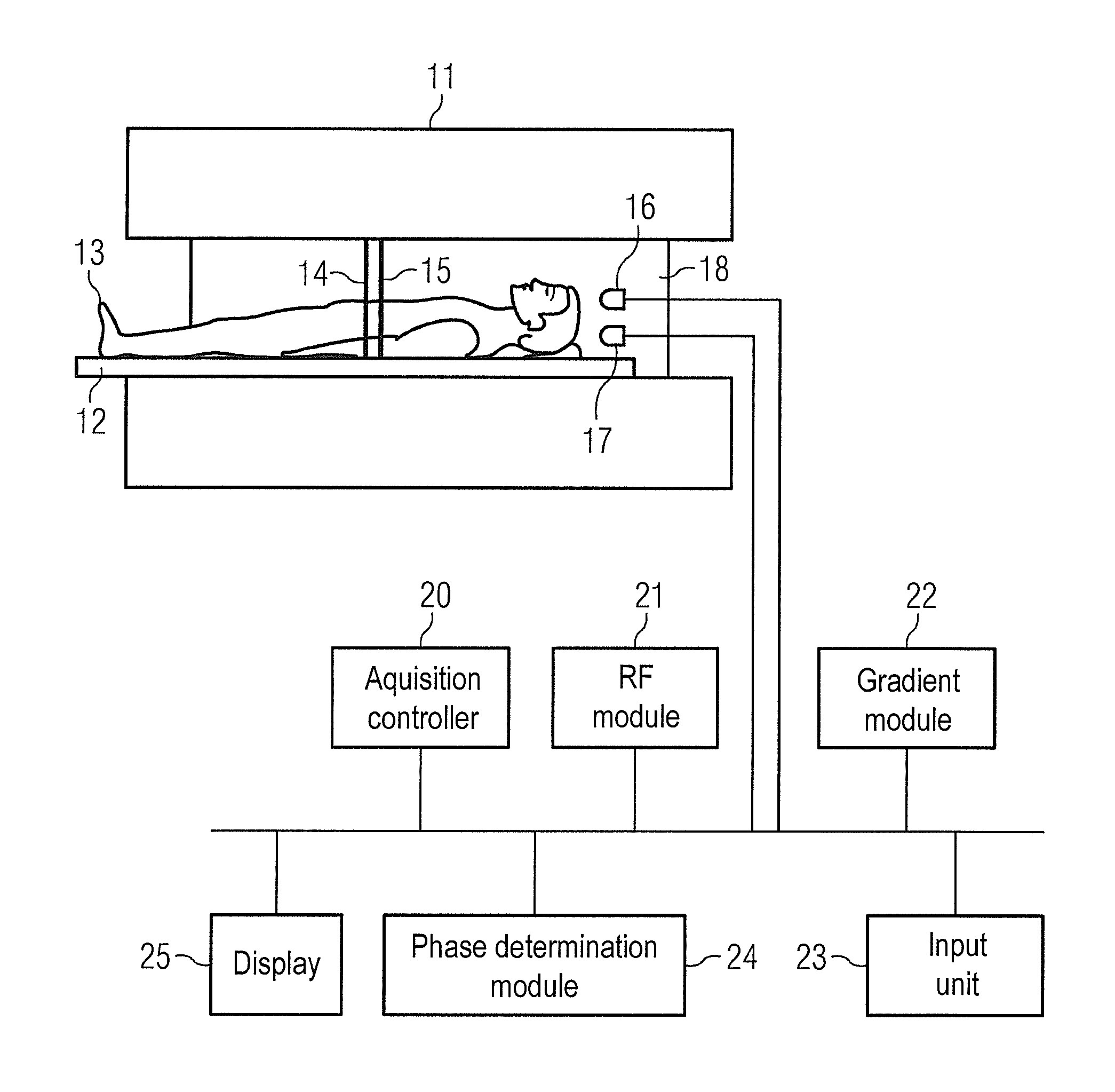
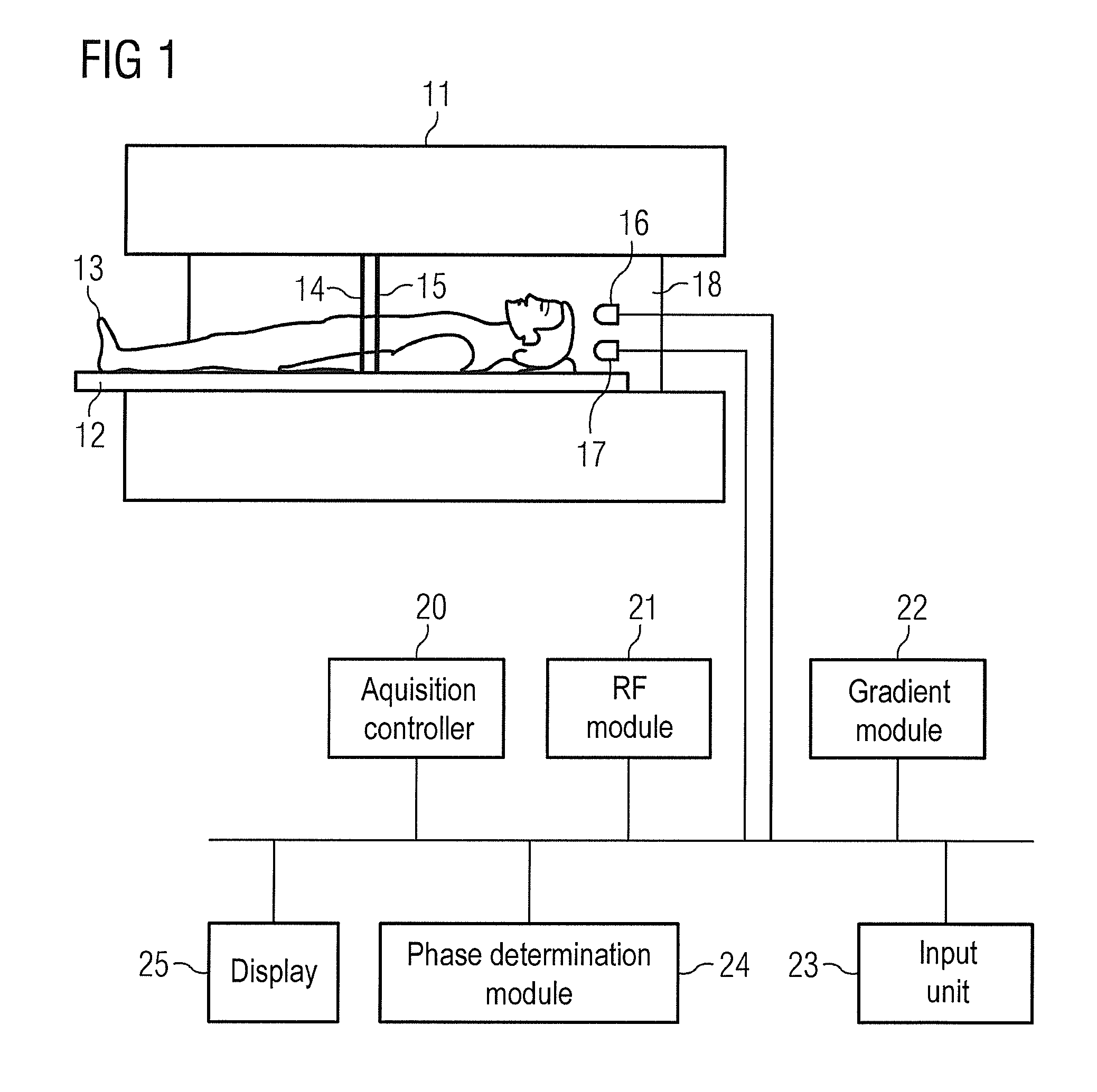
[0039]An MR system is schematically shown in FIG. 1, with which slice-individual gradient correction moments can be impressed on the individual slices according to the invention in a slice multiplexing method. In the present invention, the gradients in question are the magnetic field gradients for spatial coding. An MR system 10 with a magnet 11 to generate a polarization field B0 is shown in FIG. 1. An examined person 13 arranged on a bed 12 is driven into the MR system. Radio-frequency coil arrangements 16 and 17 with which the MR signals can be detected from the two different slices 14 and 15 are schematically shown to detect MR image data from said first slice 14 and second slice 15. The MR system furthermore has a gradient system 18 in order to achieve a spatial coding with the RF pulses emitted by the RF coils 16 and 17. As is known, the resulting magnetization in the two slices 14 and 15 points in the direction of the basic magnetic field before radiation of RF pulses. Via th...


PUM


Abstract

In a method to correct a signal phase in the acquisition of MR signals of an examination subject in a slice multiplexing method, in which MR signals from at least two different slices of the examination subject are detected simultaneously in the acquisition of the MR signals, a linear correction phase in the slice selection direction is determined for each of the at least two slices. An RF excitation pulse with a slice-specific frequency is radiated in each of the at least two different slices. A slice selection gradient is activated during a slice selection time period, during which the different RF excitation pulses are radiated in the at least two different slices, and the slice selection time period has a middle point in time in the middle of the slice selection time period, and the different RF excitation pulses temporally overlap for the at least two different slices. A time offset of the RF excitation pulse relative to the middle point in time for each of the RF excitation pulses is determined, such that a slice-specific correction gradient moment in the slice selection direction that corresponds to the linear correction phase of the respective slice acts on the magnetization of the respective slice.

Description

BACKGROUND OF THE INVENTION[0001]1. Field of the Invention[0002]The present invention concerns a method to correct a signal phase in the acquisition of MR signals of an examination subject in a slice multiplexing method, and an MR system for implementing such a method.[0003]2. Description of the Prior Art[0004]The desire for ever faster MR acquisitions in the clinical environment is currently leading to a renaissance of methods in which multiple images are acquired simultaneously. In general, these methods can be characterized in that transverse magnetization of at least two slices is specifically used simultaneously for the imaging process (“multislice imaging”, “slice multiplexing”), at least during a portion of the measurement. In contrast to this, in the established “multislice imaging” the signal is acquired from at least two slices in alternation, i.e. completely independently of one another with correspondingly longer measurement time. For example, the following are among suc...

Claims


Application Information

Patent Timeline
IPC IPC(8): G01R33/56
CPCG01R33/56G01R33/288G01R33/4835G01R33/56563G01R33/56572G01R33/56581
Inventor FEIWEIER, THORSTEN
Owner SIEMENS HEALTHCARE GMBH
Why Eureka
Try Eureka