

Power transistor drive circuit
- Summary
- Abstract
- Description
- Claims
- Application Information
AI Technical Summary
Benefits of technology
Problems solved by technology
Method used
Image

Examples
first embodiment
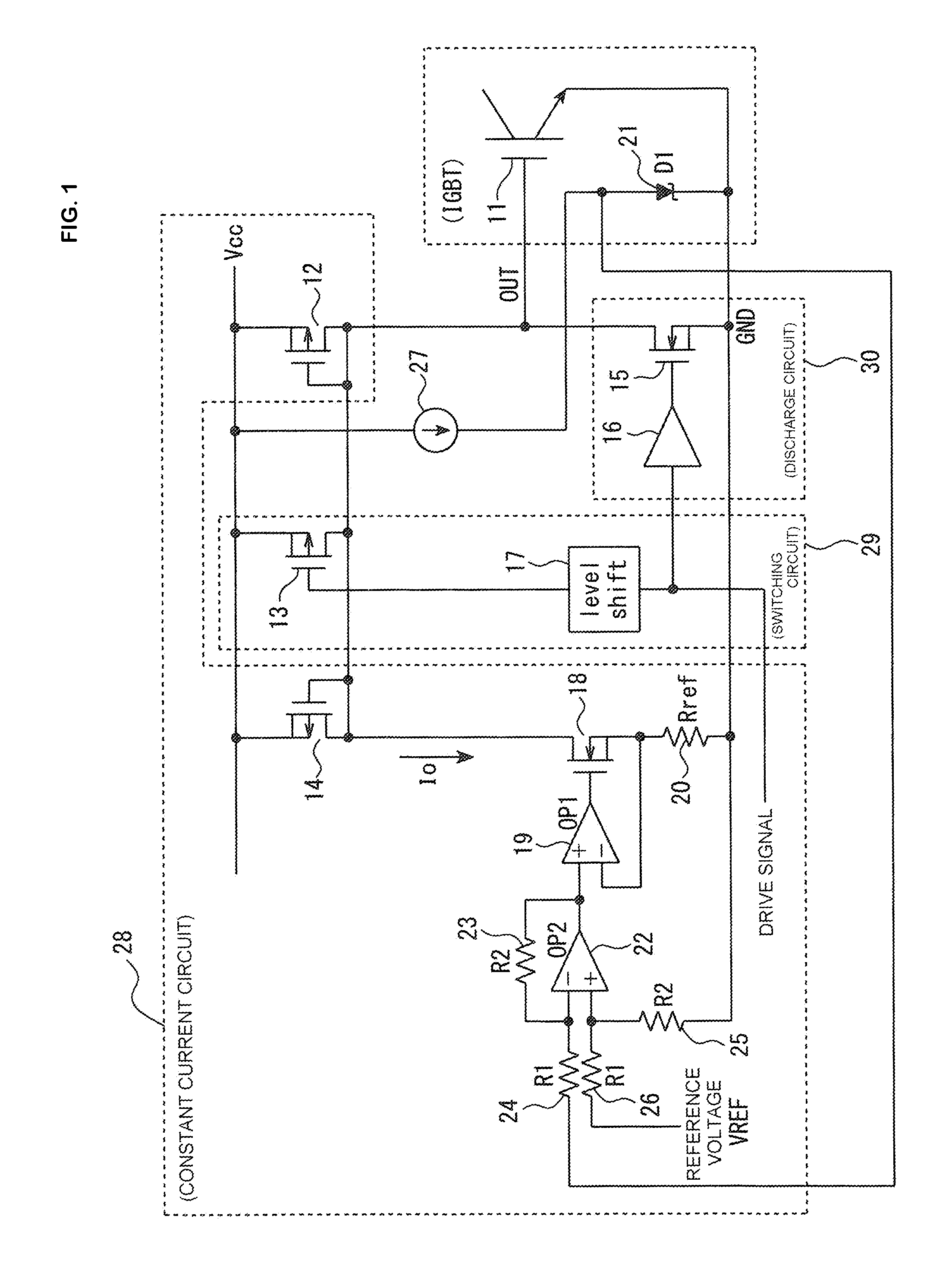
[0033]FIG. 1 is a configuration diagram of a power transistor drive circuit according to a first embodiment of the invention. Firstly, a description will be given of a configuration of the power transistor drive circuit shown in FIG. 1. As shown in FIG. 1, the power transistor drive circuit includes a constant current circuit 28, a switching circuit 29, and a discharge circuit 30.
[0034]The constant current circuit 28 includes a P-FET 12, a P-FET 14, an N-FET 18, a resistor 20, a resistor 23, a resistor 24, a resistor 25, a resistor 26, a first operational amplifier 19, and a second operational amplifier 22. The P-FETs 12 and 14 are turned off when a high level is input into the gates thereof, and turned on when a low level is input into the gates thereof.
[0035]A power source Vcc is connected to the source of the P-FET 12. The drain of an N-FET 15 is connected to the drain of the P-FET 12. The gate and drain of the P-FET 12 are connected together. The gate of an IGBT (a power transis...
second embodiment
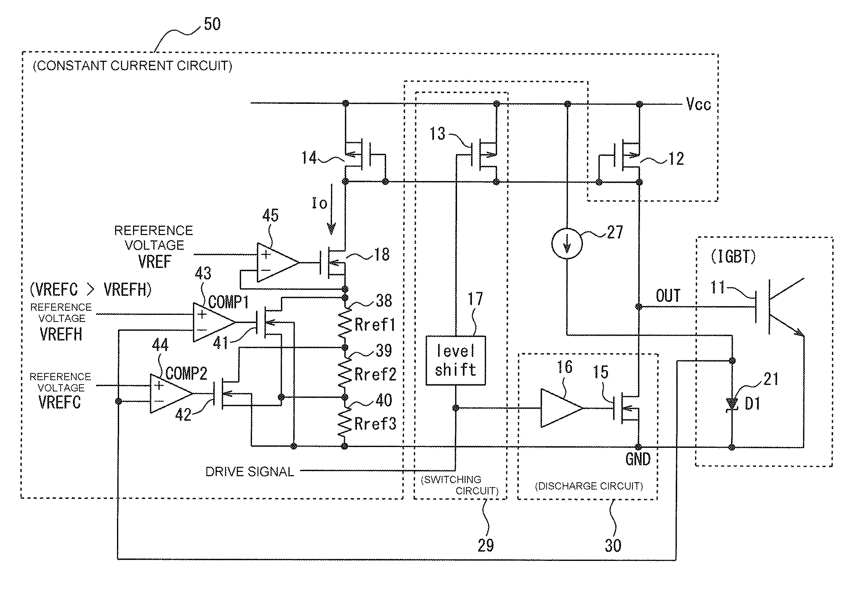
[0059]FIG. 3 is a diagram showing a power transistor drive circuit according to a second embodiment, and the same reference numerals and signs are given to components substantially the same as the components in FIG. 1. In the second embodiment, an operational amplifier 45 is used in place of the operational amplifier 19 in FIG. 1, and comparators 43 and 44 are used in place of the operational amplifier 22. Also, the resistor 20 in FIG. 1 is divided into three, a resistor 38, a resistor 39, and a resistor 40.
[0060]As shown in FIG. 3, the power transistor drive circuit of the second embodiment includes a constant current circuit 50, the switching circuit 29, and the discharge circuit 30. The constant current circuit 50 is different in configuration from the constant current circuit 28 in FIG. 1.
[0061]That is, the constant current circuit 50 of the second embodiment includes the P-FET 12, the P-FET 14, the N-FET 18, an N-FET 41, an N-FET 42, and the operational amplifier 45, and furthe...
PUM
 Abstract
Description
Claims
Application Information