Interferometric method and digital holographic microscope

a technology of interferometry which is applied in the field of interferometry methods and digital holographic microscopes, can solve problems such as unmaturized techniques

Active Publication Date: 2013-10-31
CANON KK +1
View PDF4 Cites 33 Cited by
  • Summary
  • Abstract
  • Description
  • Claims
  • Application Information

AI Technical Summary

Benefits of technology

[0014]According to another aspect of the present invention, a digital holographic microscope comprises a laser source configured to emit a laser beam; a beam splitter configured to split the laser beam into an object beam passing thorough a sample at an incident angle and a reference beam; a condenser configured to irradiate the sample with the object beam; an objective, the condenser and the object lens being arranged along an optical axis; a beam angle controller configured to rotate the object beam around the optical axis while maintaining the incident angle in order to form a plurality of interference patters; and a detector configured to detect the interference patterns.
[0015]According to another aspect of the present invention, an interferometric method for obtaining information about refractive index of a sample comprises preparing an object beam passing through a sample and a reference beam; forming an interference pattern with a fringe pitch by combining the object beam with the reference beam; detecting the interference pattern; and scanning the object beam to detect a plurality of interference patterns while maintaining the fringe pitch.

Problems solved by technology

Applying the off-axis method to the field of three dimensional measurements is a relatively new technique, and the technique is not matured yet.

Method used


Image

  • Interferometric method and digital holographic microscope
  • Interferometric method and digital holographic microscope
  • Interferometric method and digital holographic microscope

Examples


first embodiment

Circular Scan

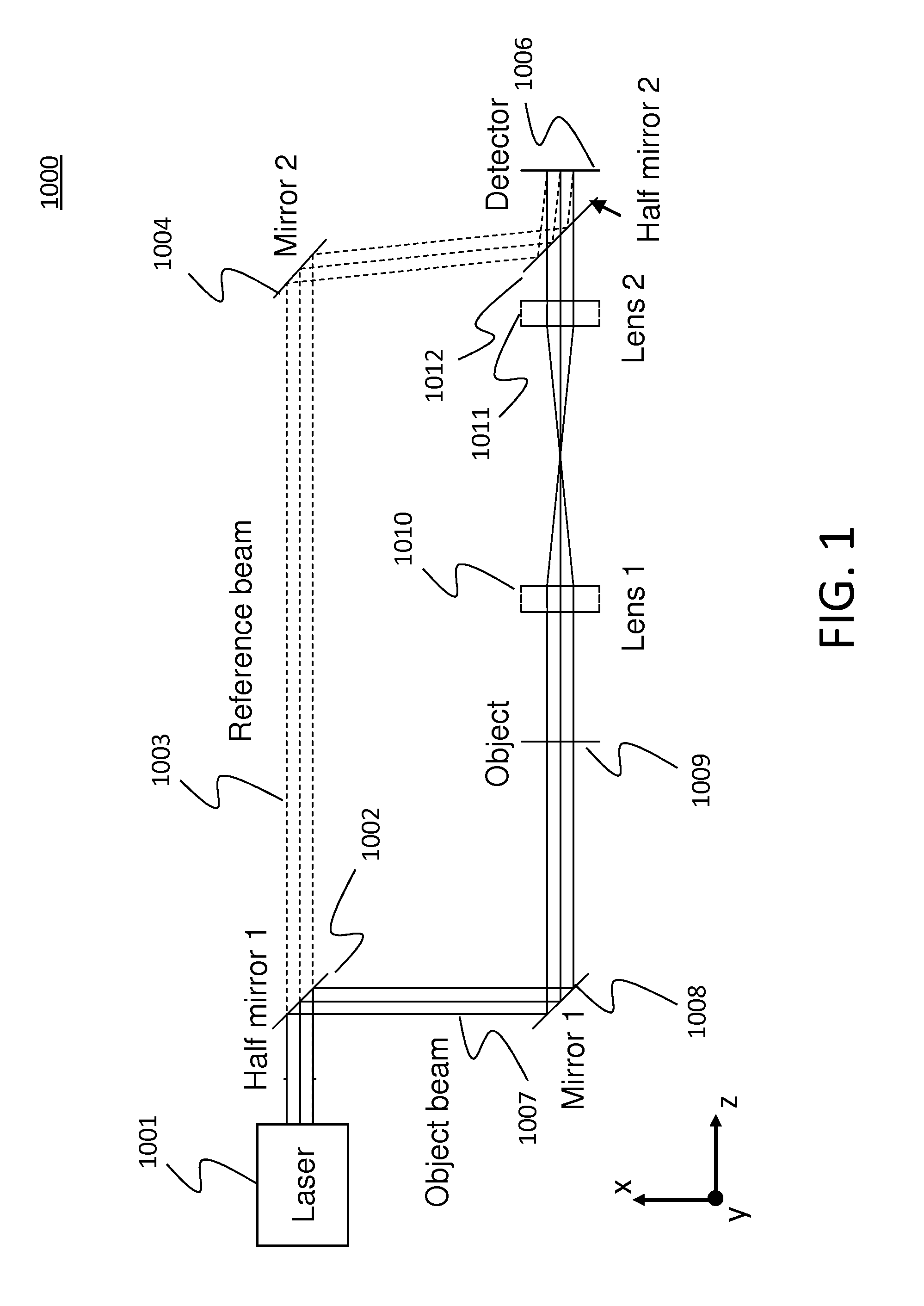
[0056]A system 1000 for performing the off-axis method is illustrated in FIG. 1. A display and a computer, which are not shown, can be used as the digital holographic microscope. A beam from a laser 1001 is split into a reference beam 1003 and an object beam 1007 by a half mirror 1002. The reference beam 1003 travels to the detector 1006 via a mirror 1004 and a half mirror 1012. As shown in FIG. 1, the object beam 1007 travels to an object (sample) 1009 via a mirror 1008. The object beam 1007 then travels through the object 1009 to the detector 1006 via two lenses 1010 and 1012, and a half mirror 1012. The object can be, for example, living or non-living cells, tissues, or organisms.

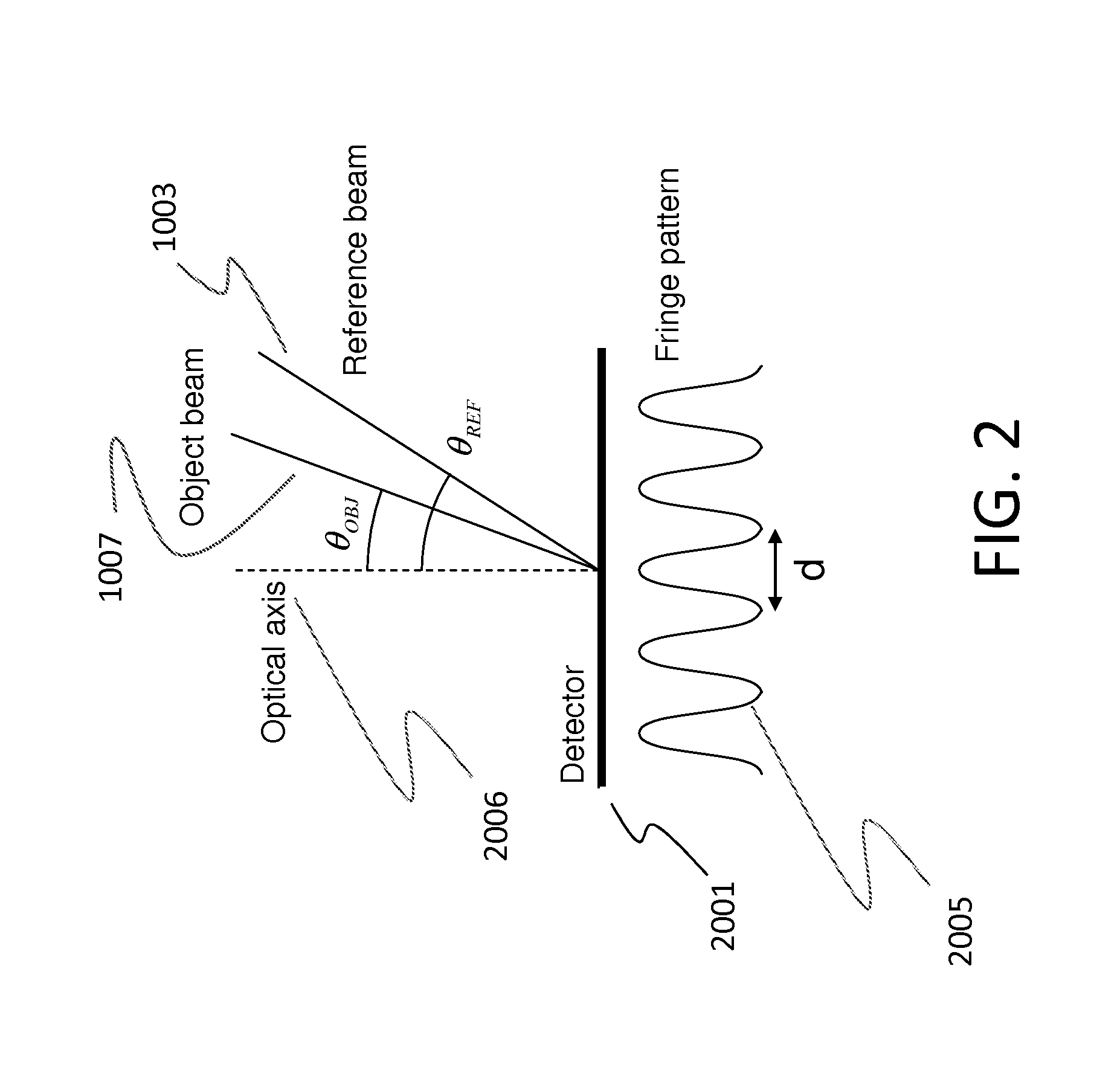
[0057]The phase information of the object 1009 is measured as an interference pattern (i.e., a fringe pattern) formed by the object beam 1007 and the reference beam 1003. To form the interference pattern on the detector 1006, the reference beam 1003 is not perfectly parallel to the object be...

second embodiment

Spiral Scan

[0110]The following configuration in this embodiment is based on the off-axis method.

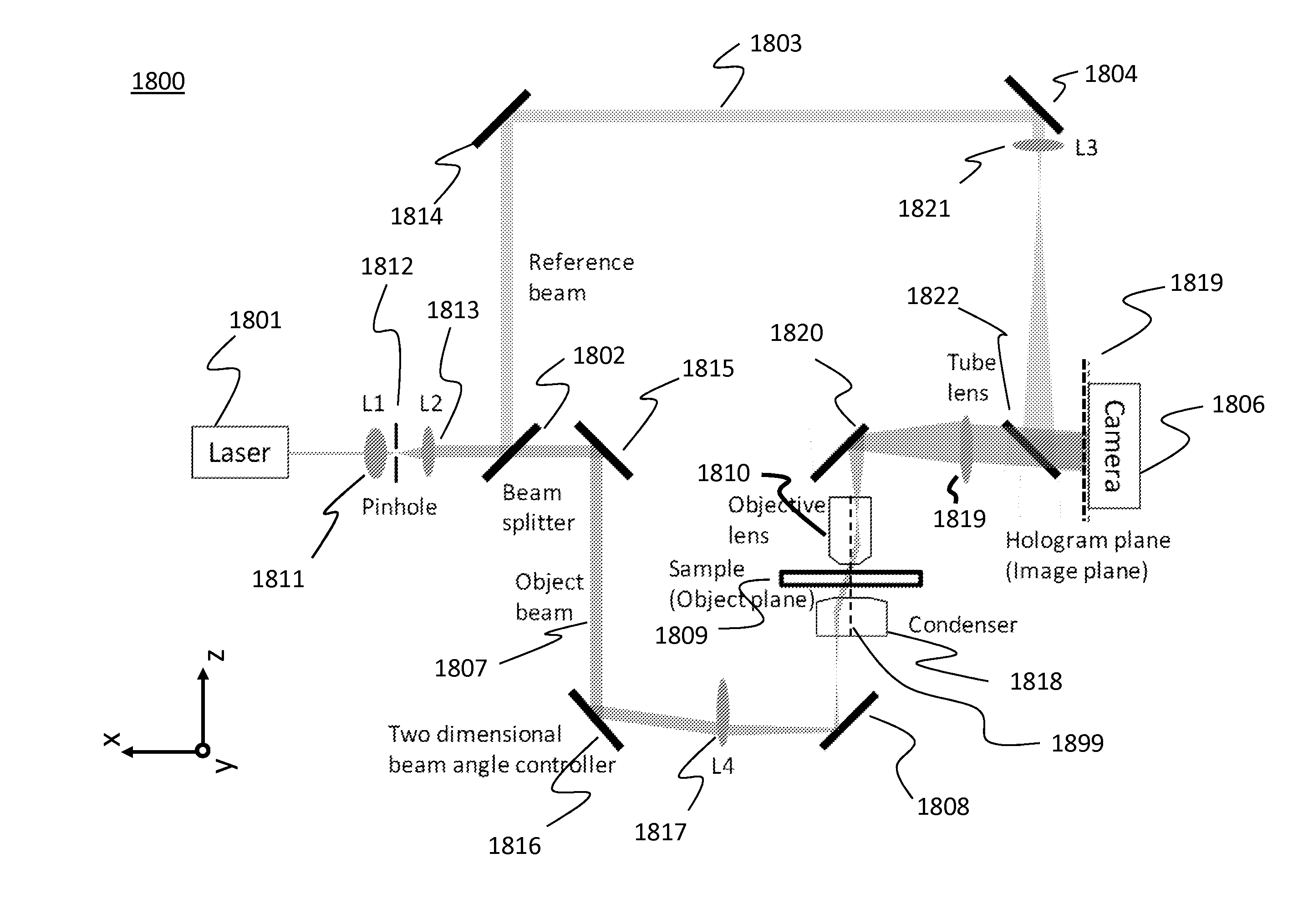
[0111]In FIG. 20, a system 2800 separates an incident light emitted from a laser source 2801 into two beams by a first beam splitter 2802, and integrates them by a second beam splitter 2812. Lens units (2814, 2815, 2816, and 2817) can be used in the system. One beam can be called an object beam 2807, and the other can be called a reference beam 2803. A sample 2809 is located at the object beam side. The object beam 2807 is tilted by a Galvanometer mirror 2808. This tilt makes an angle between the object and reference beams on the detector 2806 in order to generate fringe patterns on the detector 2806. The fringe pattern is recorded as digital holograms.

[0112]By changing the angle of the Galvanometer mirror 2808, the incident angle of the object beam 2807 against the sample 2809 can be controlled. By controlling this incident angle, the sample 2809 can be scanned with a lot of angles so th...

third embodiment

Scanning Both Beams

[0126]In this embodiment, a method for controlling an angle of the reference beam while changing an illumination angle of the object beam is described.

[0127]In FIG. 27, the off-axis holography system 2700 is illustrated. A beam from a laser source 2701 is split into an object beam 2709 and a reference beam 2703 by a half mirror 2702. The object beam 2709 travels to a detector 2707 via a scanning mirror 2710, a lens 2711, a lens 2712, an object 2750, a lens 2713, a lens 2714, and a half mirror 2708. The reference beam 2703 travels to the detector 2707 via a scanning mirror 2704, a lens 2705, a lens 2706, and the half mirror 2708. A fringe pattern formed by the object and reference beams can be detected by the detector 2707.

[0128]Lenses 12711 and 22712 make the mirror 2710 and the object 2750 conjugate so that tilting the mirror 2710 doesn't change the position of the beam in the object 2750. A lens 32713 is an objective lens, and a lens 42714 is a tube lens, and th...


PUM


Abstract

An interferometric method for detecting information about a sample includes emitting a laser beam; splitting the laser beam into a reference beam and an object beam; transmitting the object beam through the sample in an incident angle; combining the reference beam with the object beam passed through the sample to form an interference pattern; detecting the interference pattern, and non-linearly scanning the object beam in order to detect a plurality of interference patterns.

Description

BACKGROUND OF THE INVENTION[0001]1. Field of the Invention[0002]The present invention relates to an interferometric method for detecting information about a sample and a digital holographic microscope.[0003]2. Description of the Related Art[0004]There are two major methods for a digital holographic microscope which uses holograms to reconstruct an image of an object. One is a phase shift method (i.e., on-axis method), and the other is an off-axis method.[0005]The on-axis method usually requires a plurality of holograms (e.g., four holograms) to observe the object from a direction and reconstruct the object image, because only one hologram cannot show whether the phase of the incident beam is delayed by the existence of the object.[0006]Accordingly, the plurality of holograms are formed by using several reference beams whose phases are than different each other. In the on-axis method, the light intensity information of an image on the detector, which is obtained with each reference b...

Claims


Application Information

Patent Timeline
Patent Type & Authority Applications(United States)
IPC IPC(8): G01B9/02G01B9/023G01B11/24
CPCG01N21/453G02B21/0052G03H2001/005G03H2001/0456G03H2001/046G03H2222/36G03H2222/44G03H1/0443
Inventor MATSUBARA, ISAOYU, CHUNG-CHIEHUNNO, YASUYUKIDALLAS, WILLIAM
Owner CANON KK
Why Eureka
Try Eureka