
Vortex light lighting-based dark field digital holographic microscopy device and method

A digital holographic microscope and vortex light technology, applied in the field of digital holography, can solve the problems of reducing the contrast and resolution of system imaging, weakening the intensity of illumination light, strong diffraction effect, etc., achieving high contrast, improving imaging resolution, and improving resolution rate effect

Inactive Publication Date: 2015-04-29
NANJING NORMAL UNIVERSITY
View PDF7 Cites 18 Cited by
  • Summary
  • Abstract
  • Description
  • Claims
  • Application Information

AI Technical Summary

Problems solved by technology

However, the energy of the Gaussian beam is mainly concentrated in the central area of ​​the spot. The above-mentioned methods only retain the ring-shaped part of the edge, and lose most of the energy, resulting in the weakening of the intensity of the illumination light; moreover, the illumination light produced by these methods is diffracted during propagation. The side lobe is relatively strong, and it is easy to be reflected by the inner wall of the tube mirror to generate stray light, which causes background noise during imaging; at the same time, it produces a strong diffraction effect when imaging small objects
The existence of these factors reduces the contrast and resolution of system imaging

Method used


Image

  • Vortex light lighting-based dark field digital holographic microscopy device and method
  • Vortex light lighting-based dark field digital holographic microscopy device and method
  • Vortex light lighting-based dark field digital holographic microscopy device and method

Examples


Embodiment Construction

[0032] The present invention will be further described below in conjunction with the accompanying drawings.

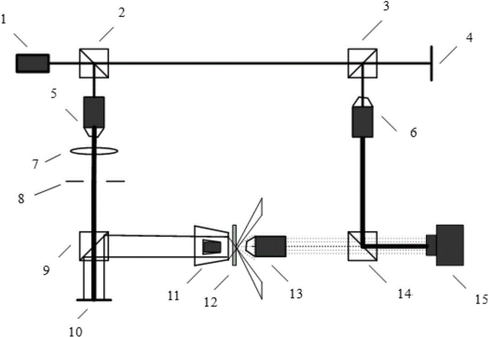
[0033] Such as figure 1 As shown, the device of the present invention includes laser 1, beam splitting prism I 2, beam splitting prism II 3, plane mirror 4, microscopic objective lens spatial filter 5, microscopic objective lens 1 6, Fourier lens 7, diaphragm 8, Dichroic prism III 9 , spatial light modulator 10 , dark field microscope objective 11 , small ball sample 12 , microscopic objective II 13 , dichroic prism IV 14 and photocoupler 15 .

[0034] Wherein, the laser 1 is 0.18m apart from the beam-splitting prism I 2 in the horizontal direction; the beam-splitting prism II 3 is 1.05m away from the beam-splitting prism I 2 in the horizontal direction; The objective spatial filter 5 is 0.16m from the beamsplitter prism I 2 in the vertical direction; the microscopic objective I6 is 0.17m from the beamsplitter prism II 3 in the vertical direction; the front focal plane ...


PUM


Abstract

The invention provides a vortex light lighting-based dark field digital holographic microscopy device and a vortex light lighting-based dark field digital holographic microscopy method. The device comprises a laser, a beam splitting prism I, a beam splitting prism II, a plane reflecting mirror, a microscope objective spatial filter, a microscope objective I, a Fourier lens, a diaphragm, a beam splitting prism III, a spatial light modulator, a dark field microscope objective, a small ball sample, a microscope objective II, a beam splitting prism IV and an photoelectric coupling device. The method comprises three steps: first, lighting an object by utilizing an annular light cone formed by vortex light after the vortex light enters the dark field microscope objective; then, recording interference fringes of scattered light of the object and reference light into a computer through the photoelectric coupling device by a digital holographic technology; finally, reconstructing the image of the object by utilizing a digital reconstructing technology. Compared with the traditional bright field digital holographic microscopy imaging method, the device and the method have the advantages of high resolution, high contrast and the like, and are applicable to the field of researching the characteristics of a vortex light beam, observing a small phase object and the like in a laboratory.

Description

technical field [0001] The invention relates to a dark-field digital holographic technique for recording the interference fringes of the scattered light of a small ball and spherical wave reference light when illuminated by vortex light, and specifically relates to a dark-field digital holographic microscopic device and method based on vortex light illumination, belonging to Digital holography field. Background technique [0002] Digital holography technology is the product of the combination of computer technology and traditional optical holography. Using digital recording and reproduction methods, the amplitude information and phase information of objects can be obtained more conveniently. Digital holography is replaced by photoelectric sensor devices (such as CCD or CMOS) The hologram is recorded on the dry plate, and then the hologram is stored in the computer, and the computer is used to simulate the optical diffraction process to realize the holographic reproduction an...

Claims


Application Information

Patent Timeline
Patent Type & Authority Applications(China)
IPC IPC(8): G01B9/021
Inventor 冯少彤张秀英赵应春袁操今聂守平
Owner NANJING NORMAL UNIVERSITY
Learn More