
Digital holographic microscopy device based on local hollow beam illumination and working method thereof

A local hollow beam, digital holographic microscopy technology, applied in the research field, can solve the problems of poor controllability, weak imaging contrast, loss of light energy, etc., to achieve high contrast, improve imaging contrast, and improve imaging resolution.

Inactive Publication Date: 2018-04-13
KUNMING UNIV OF SCI & TECH
View PDF1 Cites 16 Cited by
  • Summary
  • Abstract
  • Description
  • Claims
  • Application Information

AI Technical Summary

Problems solved by technology

[0003] The technical problem to be solved by the present invention is to provide a digital holographic microscope device based on local hollow beam illumination and its working method, in order to overcome the inner and outer radius of the ring-shaped illumination light existing in the existing dark-field digital holographic microscopy illumination light The invention can effectively improve the resolution of the system and enhance the contrast of the reproduced image due to problems such as poor controllability of the ring diameter ratio, uneven light waves, weak imaging contrast, and a large loss of light energy.

Method used


Image

  • Digital holographic microscopy device based on local hollow beam illumination and working method thereof
  • Digital holographic microscopy device based on local hollow beam illumination and working method thereof
  • Digital holographic microscopy device based on local hollow beam illumination and working method thereof

Examples


Embodiment 1

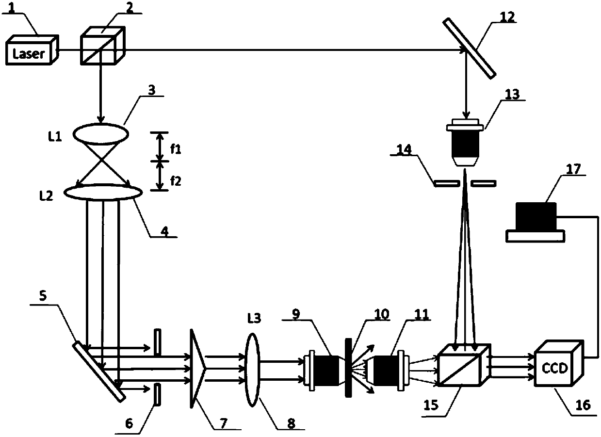
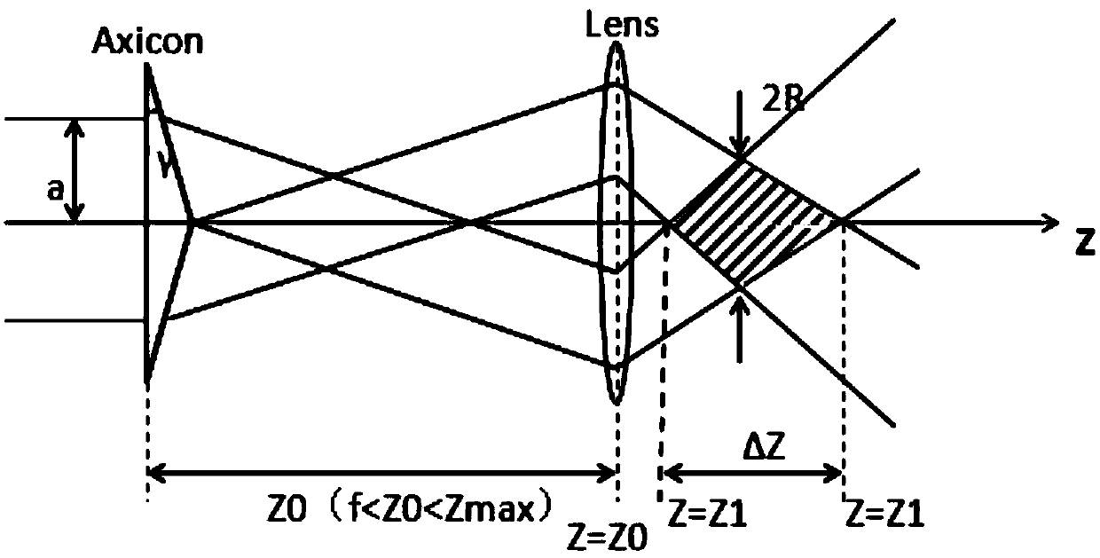
[0040] Embodiment 1: as Figure 1-8 As shown, a dark-field digital holographic microscope device based on local hollow beam illumination, including a laser 1, an optical beam splitter I 2, an optical beam splitter II 15, a microscope objective I 11, a microscope objective II 13, Pinhole filter 14, optical mirror I 5, optical mirror II 12, first lens L1 3, second lens L2 4, third lens L3 8, diaphragm 6, cone mirror 7, dark field condenser 9, experiment Sample 10, optocoupler device 16, computer 17; wherein the laser light emitted by laser 1 is irradiated on optical beam splitter I 2; optical beam splitter I 2, optical beam splitter II 15, optical reflector I 5 and optical reflector II 12 forms a Mach-Zehnder optical path system on the optical platform, wherein the optical beam splitter I 2 is on the same horizontal line as the optical mirror II12, and the optical beam splitter I 2 is on the same vertical line as the optical mirror I 5 , the optical mirror II12 and the optical ...


PUM

PropertyMeasurementUnit
Diameteraaaaaaaaaa

Abstract

The invention, which belongs to the field of digital holographic microscopy (DHM), relates to a digital holographic microscopy device based on local hollow beam illumination and a working method thereof. The digital holographic microscopy device is composed of a laser device, an optical beam splitter I, an optical beam splitter II, an optical reflector I, an optical reflector II, a dark field condenser, a microscope objective I, a microscope objective II, a spatial filter, a first lens L1, a second lens L2, a third lens L3, a computer, and other components. The digital holographic microscopy device is implemented as follows: after incidence of a generated local hollow light beam to the dark field condenser, an annular light cone illumination experiment sample is formed; with the digital holography, interference fringes of diffracted light and reference light of the sample are recorded to the computer by an optocoupler device; and then on the basis of a reconstructive technique, a three-dimensional image of an object is reproduced. Compared with the traditional digital holographic microscopy, the digital holographic microscopy device provided by the invention has the higher resolution and contrast ratio and is suitable for microcosmic fields such as observation of living cells and solvent particles in biomedical detection.

Description

technical field [0001] The present invention relates to a kind of digital holographic microscope technology recording the interference fringes of scattered light and spherical wave reference light obtained by illuminating experimental samples with localized hollow beams, in particular to a digital holographic microscope device and its working method based on localized hollow beams illumination , belonging to the field of digital holographic microscopy (DHM). The invention is applicable to research fields such as biology, biomedical detection, and environmental science. Background technique [0002] Digital holographic microscopy (DHM), which has been developed in recent years, has the advantages of low cost, simple operation, and can simultaneously obtain the quantitative intensity and position image information of the sample. This technology can be used for convenient filtering, phase distortion correction, automatic focusing, and expansion. Depth of focus and other operat...

Claims


Application Information

Patent Timeline
IPC IPC(8): G02B21/10G02B21/36G02B27/09G03H1/00G03H1/12
CPCG02B21/10G02B21/365G02B27/0927G02B27/0955G03H1/0005G03H1/12G03H2001/005G03H2001/045G03H2222/35G03H2001/0452G03H1/0443G03H1/0465
Inventor 张文燕楼宇丽李重光
Owner KUNMING UNIV OF SCI & TECH
Learn More