Digital holographic microscope with fluid systems

a holographic microscope and fluid system technology, applied in the field of digital holographic microscopes with fluid systems, can solve the problems of insufficient accuracy of the apparatus, time-consuming and/or laborious gathering and preparing of samples for further observation or analysis, and achieve the effect of convenient manufactur

Active Publication Date: 2018-02-27
OVIZIO IMAGING SYST NV SA
View PDF77 Cites 16 Cited by
  • Summary
  • Abstract
  • Description
  • Claims
  • Application Information

AI Technical Summary

Benefits of technology

[0033]In a preferred embodiment, the present invention provides a fluid microscope system as described above, whereby at least one fluidic system comprises a reactor attachment system for easily attaching and / or detaching said fluidic system to said reactor, whereby leakage of fluid is prevented.
[0043]In a preferred embodiment, the present invention provides a package system as described above, whereby said package encloses said tube, thereby protecting said tube against external contamination.

Problems solved by technology

In the former case, typical problems are e.g. that the analysis apparatus needs to be resistant to the specific environment in the reactor, that the apparatus, when reused with another reactor, does not contaminate this other reactor, that the analysis apparatus is very expensive, that the apparatus is not accurate enough, etc.
; in the latter case, a typical problem is the often time-consuming and / or labor-intensive gathering and preparing of samples for further observation or analysis.
In such cases, it may be impossible to accurately monitor the state and / or processes of the reactor, as the time delay between the gathering of a sample and the analysis results may become too big.
However, traditional flow microscopes do not always provide enough information on the objects suspended in a flow.
Even though these two techniques are widely used in biological microscopy, and well suited as contrasting methods, they cannot be used for precise quantitative phase measurements.
However, whereas interferometric techniques are widely used in metrology, only few biological applications have been reported, by R. Barer and S. Joseph, in “Refractometry of living cells”, Quarterly Journal of Microscopical Science, Vol. 95, 1954, pp.
The main advantage originates from the fact that complex and costly experimental optical devices can be handled by digital processing methods.
However, the above mentioned prior art DHI techniques do not disclose how one can obtain data from an extensive sample of objects suspended in a fluid, nor the possibility of obtaining such data within a relatively short period.
The problems in the prior art are multiple.
The data acquired with the analysis apparatus of the prior may not be accurate enough, it may not be obtained quickly enough, the apparatus may be too expensive, it may only give two-dimensional and / or analogue images whereby three-dimensional information is obtained only after e.g. making a set of 2D images, digitalization and performing a CT-processing step.
More in particular, DHMs may provide images and / or directly digitalized information about samples which is superior to other imaging or analysis techniques, but can be rather expensive.
Furthermore, the gathered sample may need to be processed before analysis, which can be a time-consuming and labor-intensive procedure.
Contamination may be an issue when the same apparatus is used to monitor or analyze different reactors, or the same reactor at different positions of times. Prior art techniques may not always provide the possibility of returning the sample to the reactor or to another reactor, or the possibility of real-time monitoring and providing timely feedback for adapting the reactor's environmental parameters.

Method used


Image

  • Digital holographic microscope with fluid systems
  • Digital holographic microscope with fluid systems
  • Digital holographic microscope with fluid systems

Examples


examples

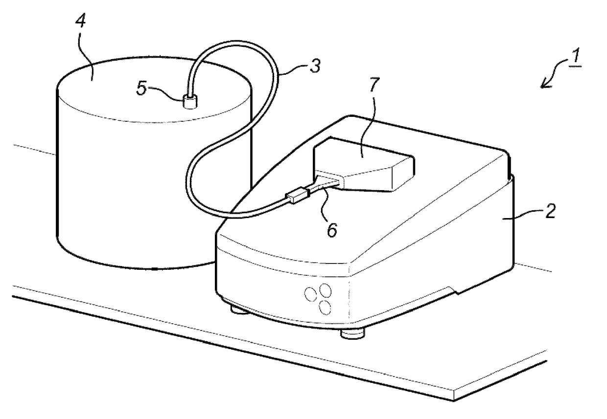
[0114]FIG. 1 illustrates a setup whereby a fluid microscope system is connected to one reactor, such as a bio-reactor. The fluid microscope system (1) comprises a DHM (2) and a fluidic system (3) which provides a fluidic connection between the DHM and a reactor (4). The fluidic system (3) is connected to the reactor (4) with a fluid-tight arrangement (5). The fluidic system (3) may comprises a number of bendable tubes inside a bendable cover, as illustrated in e.g. FIG. 3, whereby a closed fluidic circuit is formed between the reactor and the DHM, or it may comprise only one tube. Such fluidic systems (3) provide an easy connection between the reactor (4) and the DHM (2), even when it is located a certain distance away. The fluidic system (3) of FIG. 1 comprises a tube comprising a cartridge (6) which is at least partially transparent for the illumination means of the DHM and has a shape comprising two parallel transparent sides, e.g. top and bottom. This part can be easily introduc...


PUM

PropertyMeasurementUnit
sizeaaaaaaaaaa
thickaaaaaaaaaa
thickaaaaaaaaaa

Abstract

The current invention concerns a fluid microscope system for analyzing and / or monitoring the contents of one or more fluid-based reactors or canalizations such as bio-reactors, micro-reactors, brewing reactors, water supply systems or sewer systems comprising a digital holographic microscope (DHM) capable of obtaining phase information of a fluid sample and comprising illumination means and one or more fluidic systems connected to said reactors and to said DHM, capable of guiding fluid from said reactors to said DHM, whereby at least one fluidic system comprises one or more tubes which may come in direct contact with fluid from said reactor, characterized in that at least one tube comprises a part which is at least partially transparent for the illumination means of said DHM for obtaining holographic information of said fluid sample. The current invention also concerns a tube and a fluidic system for such a fluid microscope.

Description

CROSS-REFERENCE TO RELATED APPLICATIONS[0001]This application is the U.S. National Phase under 35 U.S.C. § 371 of International Application PCT / EP2013 / 069625, filed Sep. 20, 2013, which claims priority to EP 12185229.7, filed Sep. 20, 2012.TECHNICAL FIELD[0002]The invention pertains to the technical field of analyzing and monitoring the state and the processes in a reactor or incubator, using a digital holographic microscope (DHM). More in particular, the reactor may contain a fluid medium, and can be e.g. a bio-reactor containing biological organisms such as cells, bacteria, yeasts, micro-organisms, nematodes or any combination thereof in a liquid medium.BACKGROUND[0003]In biology, biotechnology, chemistry and related areas such as bio-chemistry, yeasting factories, breweries, . . . , practical use is made of reactors, containers or incubators comprising a fluid medium, or samples which contain a fluid medium, into which certain processes occur, whereby the environmental parameters...

Claims


Application Information

Patent Timeline
Patent Type & Authority Patents(United States)
IPC IPC(8): G02B21/00G03H1/00G03H1/04C12M1/34G02B21/26G03H1/02B01L3/00
CPCG03H1/0005B01L3/502715C12M41/36G02B21/0016G02B21/26G03H1/0443B01L3/50273G03H2001/0204B01L3/5027B01L2200/025B01L2200/143B01L2300/0654B01L2300/088B01L2300/0864B01L2300/0877B01L2300/123B01L2300/168B01L2400/0481G03H2001/005
Inventor MATHUIS, PHILIPJOORIS, SERGE
Owner OVIZIO IMAGING SYST NV SA
Why Eureka
Try Eureka