A Synthetic Aperture Digital Holographic 3D Microscopic Observation Device with Smooth Reflective Surface

A technology of synthetic aperture and reflective surface, applied in the direction of measuring devices, optical devices, instruments, etc., can solve the problem that the hologram of the measured surface cannot be obtained effectively, and achieve the effect of compact structure and convenient operation

Inactive Publication Date: 2011-12-14
BEIHANG UNIV
View PDF9 Cites 18 Cited by
  • Summary
  • Abstract
  • Description
  • Claims
  • Application Information

AI Technical Summary

Problems solved by technology

However, if the observation target is an object with a smooth surface, the reflected light has strong directivity. Under the illuminatio

Method used


Image

  • A Synthetic Aperture Digital Holographic 3D Microscopic Observation Device with Smooth Reflective Surface
  • A Synthetic Aperture Digital Holographic 3D Microscopic Observation Device with Smooth Reflective Surface
  • A Synthetic Aperture Digital Holographic 3D Microscopic Observation Device with Smooth Reflective Surface

Examples


Embodiment Construction

[0025] The present invention will be further described in detail below with reference to the drawings and embodiments.

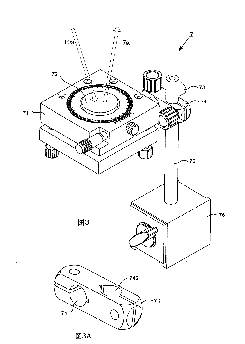
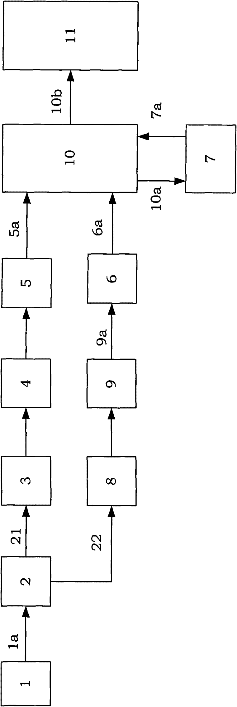
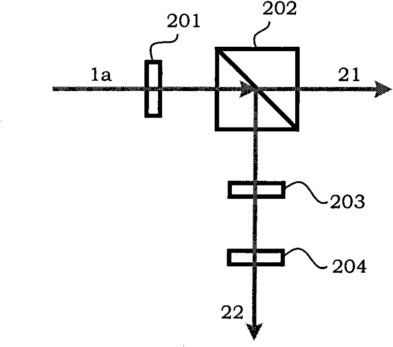
[0026] See figure 1 As shown, the present invention is a synthetic aperture digital holographic three-dimensional microscopic observation device for a smooth reflective surface. The device mainly includes a light source 1, a light splitting unit 2, a first spatial filter 3, a first plano-convex lens 4, and a third Plane mirror 5, depolarization beam splitter 10, CMOS camera 11, second spatial filter 8, second plano-convex lens 9, beam adjuster 6, rotating stage 7; among them, the first spatial filter 3 and the second The structure of the spatial filter 8 is the same; the structure of the first plano-convex lens 4 and the second plano-convex lens 9 are the same.

[0027] (1) Light source 1

[0028] In the present invention, the light source 1 is used to provide a 532nm laser 1a, that is, optical information. The light source provides a single longitudinal mode lase...


PUM


Abstract

The invention discloses a three-dimensional micro-observation apparatus for a smooth reflective surface and the apparatus is based on synthetic aperture in digital holography. The apparatus comprises a light source, light splitting unit, space filters, plano-convex lenses, a planar mirror, a depolarization beam splitter prism, a beam adjuster, a rotating stage and a complementary metal-oxide semiconductor (CMOS) camera. A light path of the apparatus is characterized in that: a laser emitted by the light source is incident to the light splitting unit; after a light splitting processing is carried out by the light splitting unit, illuminating light and reference light are output; two beams of light respectively pass through the space filters and the plano-convex lenses in order so as to be processed by beam expansion and shaping; the illuminating light passes through the planar mirror and outputs parallel light that penetrates the depolarization beam splitter prism and is incident inclinedly to a surface of an observed object on the rotating stage; and then reflected light of the object surface is again incident to the depolarization beam splitter prism; an angle and a position of the reference light are adjusted by the beam adjuster and the reference light is also incident to the depolarization beam splitter prism; and light composition processing is carried out on the incidentreference light and an object light by the depolarization beam splitter prism so as to obtain a combined light beam; and an interference hologram formed by the combined light beam is captured by a photosensitive surface of the CMOS camera. During the obtaining process, the rotating stage is rotated and an incident angle of the illuminating light is adjusted many times, so that an object surface hologram that contains different frequency components is obtained; and then fusion is carried out, thereby realizing a three-dimensional micro-observation based on the synthetic aperture in digital holography.

Description

Technical field [0001] The invention relates to a three-dimensional microscopic observation system, and more particularly, to a synthetic aperture digital holographic three-dimensional microscopic observation system for a smooth reflective surface. Background technique [0002] Digital holography technology uses photoelectric imaging detectors such as Charge Coupled Device (CCD) or Complementary Metal-Oxide Semiconductor (CMOS) to replace traditional imaging films, dry boards and other materials as recording media. The hologram is recorded by computer simulation and the reference light is then used to illuminate the hologram. Through the optical diffraction process of the simulated hologram, the three-dimensional object light field is reconstructed digitally, so as to obtain the information of the amplitude and phase of the object light field. The advantages include: (1) Obtain the three-dimensional information of the object in a non-contact manner, without pre-processing the sam...

Claims


Application Information

Patent Timeline
IPC IPC(8): G01B11/24G01B9/023
Inventor 肖文潘锋王璠璟伊小素刘烁戎路
Owner BEIHANG UNIV
Why Eureka
Try Eureka