
Instrumentation and control penetration flange for pressurized water reactor

a technology of instrumentation and control, applied in the field of nuclear reactor systems, can solve the problems of increasing the rate of nuclear reaction and core power, reducing the extent of neutron absorption, and unable to reliably operate conventional arrangement of coils

Active Publication Date: 2013-10-31
WESTINGHOUSE ELECTRIC CORP
View PDF7 Cites 45 Cited by
  • Summary
  • Abstract
  • Description
  • Claims
  • Application Information

AI Technical Summary

Benefits of technology

The patent is for a nuclear reactor with a removable annular seal ring that is attached to the reactor vessel and can be easily replaced. The seal ring is made of metal that has the same thermal expansion properties as the reactor vessel and has a plurality of holes for the passage of utility conduits. The seal ring can be forged from carbon steel or alloy 690 and has a double o-ring seal for leak detection. The technical effect of the seal ring is to provide a seal for the transport of utilities from outside the reactor vessel to the interior, while also facilitating replacement of the seal ring.

Problems solved by technology

Inserting a control rod further into the core causes more neutrons to be absorbed without contributing to the fission process in an adjacent fuel rod; and retracting the control rod reduces the extent of neutron absorption and increases the rate of the nuclear reaction and the power output of the core.
In such an arrangement, the entire control rod drive mechanism is immersed within the reactor coolant, in which the conventional arrangement of coils could not operate reliably.
Even if the coils were housed to protect them from direct contact with the coolant, conventional coils could not withstand the temperatures they would experience in an operating cycle.
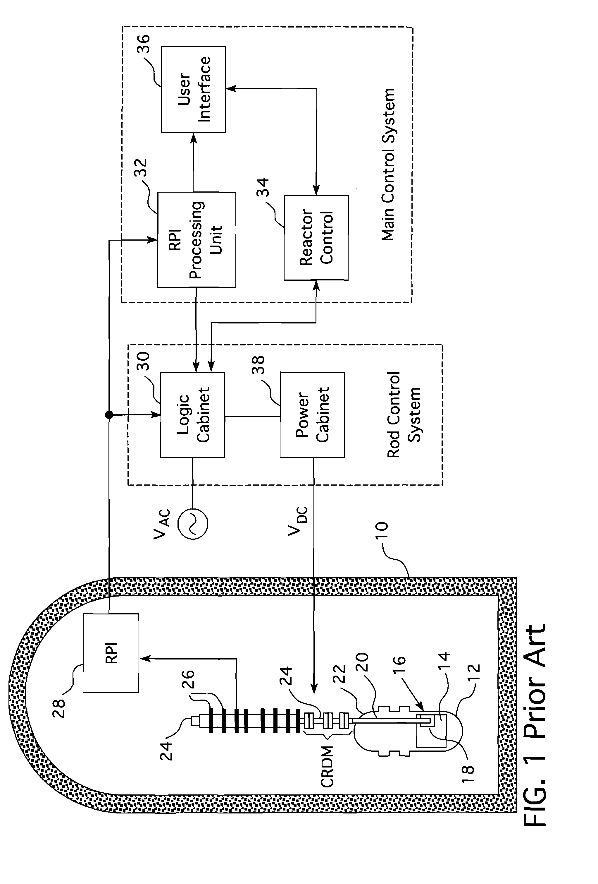
Application Ser. No. 13 / 314,519, filed Dec. 8, 2011, entitled Nuclear Reactor Internal Control Rod Drive Mechanism Assembly, overcomes those problems, however, the arrangement of components in such small modular reactors preclude the incorporation of vessel penetrations through either the upper or lower vessel heads for routing the cabling needed to power the electromagnetic CRDM coils or other in-vessel instrumentation and controls, the traditional path for supplying electrical power and transporting signals to and from internal components.
p, Pa. From the foregoing, it should be apparent that the traditional means for routing the cabling from internal components to the exterior of the reactor cannot readily be em

Method used


Image

  • Instrumentation and control penetration flange for pressurized water reactor
  • Instrumentation and control penetration flange for pressurized water reactor
  • Instrumentation and control penetration flange for pressurized water reactor

Examples


Embodiment Construction

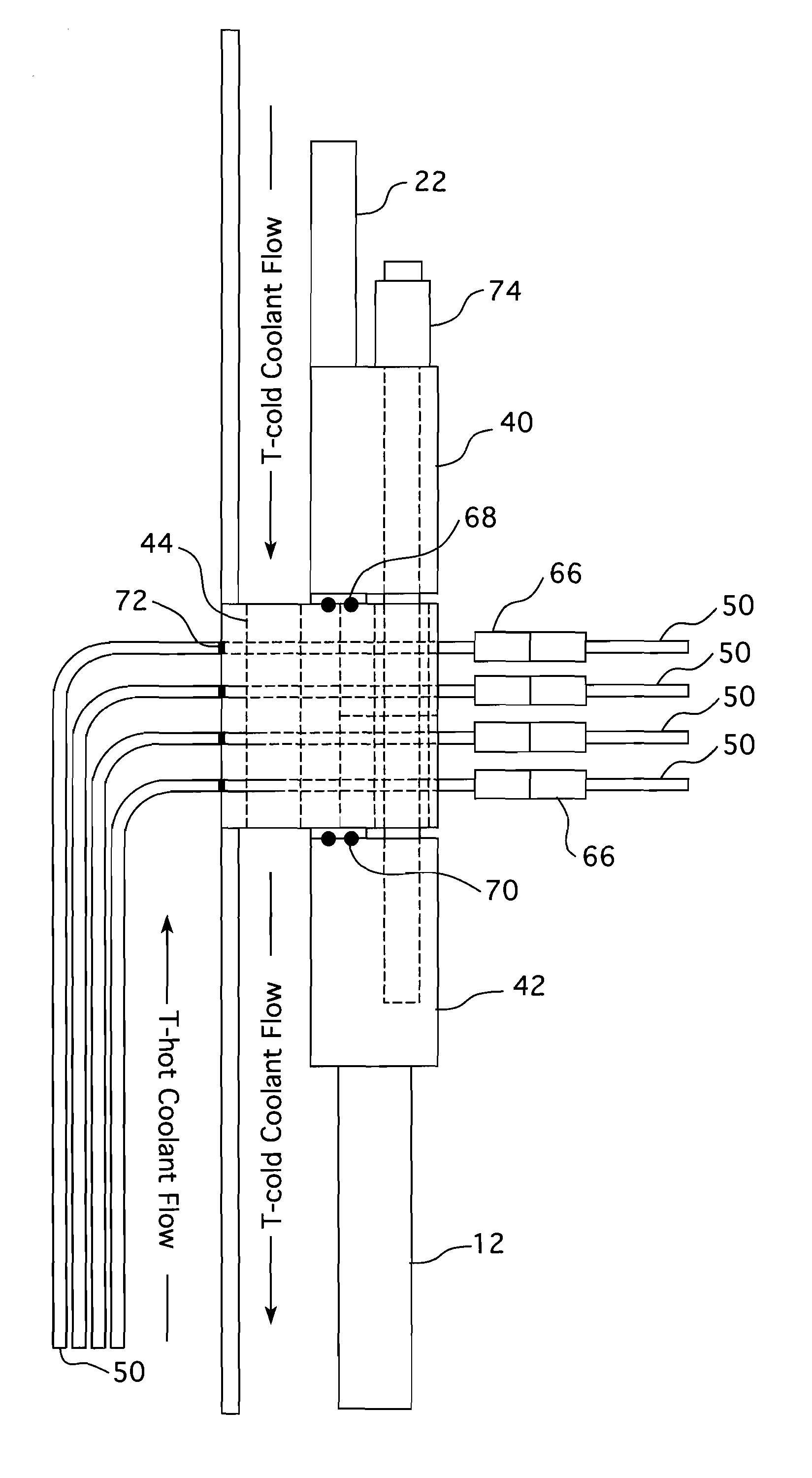
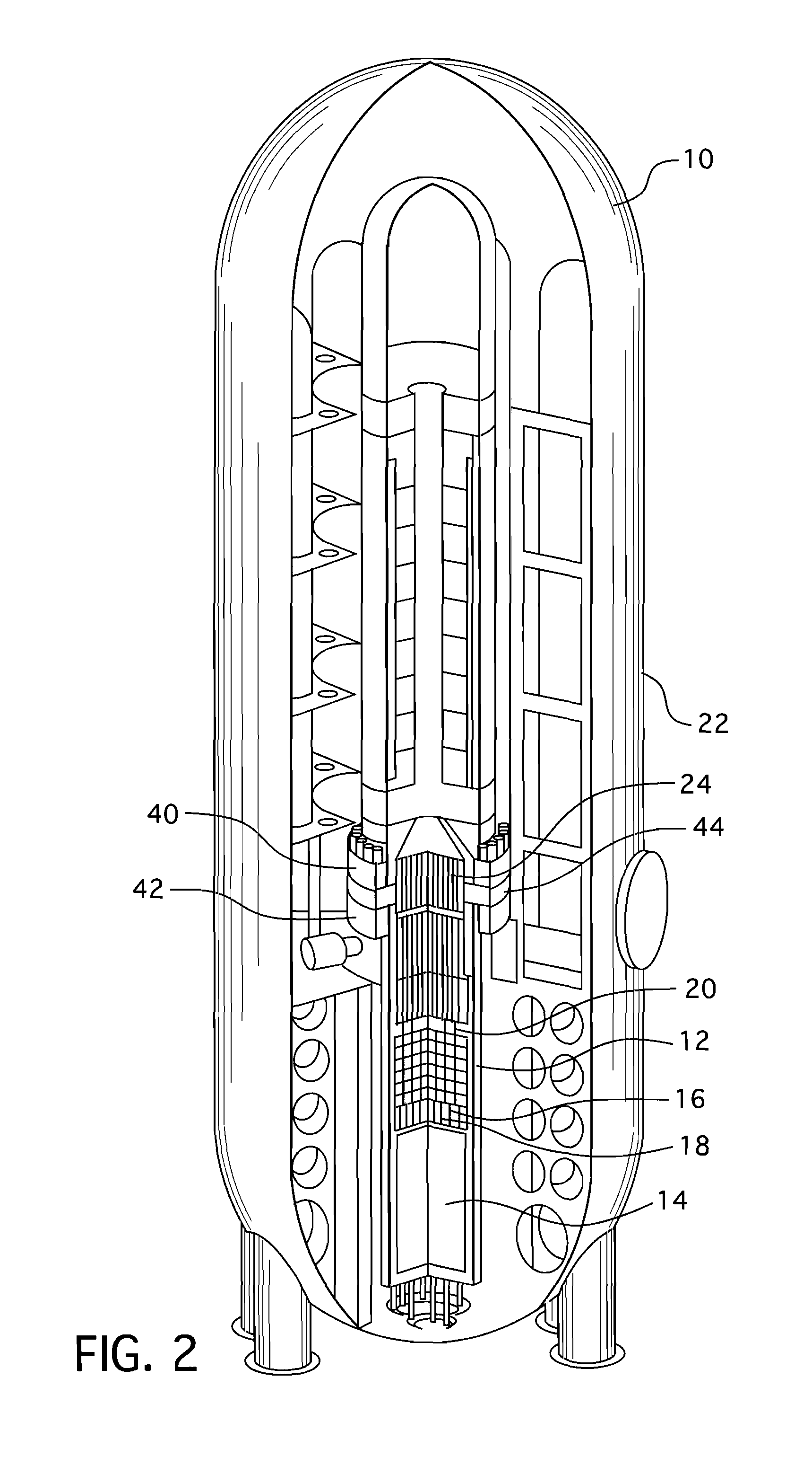
[0030]As previously mentioned, the configuration of some reactor designs, including small, integral, modular reactors, precludes the incorporation of vessel penetrations through either the upper or lower vessel heads for instrumentation and controls. Some small modular reactor designs also require electrical power supply to internal components such as control rod drive mechanism, reactor coolant pumps, and pressurizer heaters. This invention provides an alternative location for all penetrations, including electrical power, through a ring 44 that is clamped between the upper and lower reactor vessel closure flanges 40 and 42, respectively (FIGS. 2 and 3). The preferred embodiment of the invention described herein also provides a convenient means of reactor vessel disassembly and reassembly of the reactor vessel during plant refueling operations and allows for inspection and maintenance of the in-vessel components.

[0031]The following physical description of the preferred embodiment is...


PUM


Abstract

A nuclear reactor having a penetration seal ring interposed between the reactor vessel flange and a mating flange on the reactor vessel head. Radial ports through the flange provide passage into the interior of the reactor vessel for utility conduits that can be used to convey signal cables, power cables or hydraulic lines to the components within the interior of the pressure vessel. A double o-ring seal is provided on both sides of the penetration flange and partial J-welds on the inside diameter of the flange between the flange and the utility conduits secure the pressure boundary.

Description

BACKGROUND[0001]1. Field[0002]This invention relates in general to nuclear reactor systems, and, in particular to utility penetrations through a reactor vessel.[0003]2. Description of Related Art[0004]In a nuclear reactor for power generation, such as a pressurized water reactor, heat is generated by fission of a nuclear fuel such as enriched uranium, and transferred to a coolant flowing through a reactor core. The core contains elongated nuclear fuel rods mounted in proximity with one another in a fuel assembly structure, through and over which coolant flows. The fuel rods are spaced from one another in co-extensive parallel arrays. Some of the neutrons and other atomic particles released during nuclear decay of the fuel atoms in a given fuel rod pass through the spaces between fuel rods and impinge on the fissile material in adjacent fuel rods, contributing to the nuclear reaction and to the heat generated by the core.[0005]Moveable control rods are dispersed through the core to e...

Claims


Application Information

Patent Timeline
Patent Type & Authority Applications(United States)
IPC IPC(8): G21C13/00
CPCY02E30/40G21C1/322G21C17/116G21C13/028G21C13/036G21C7/12Y02E30/30
Inventor CONWAY, LAWRENCE E.HARKNESS, ALEXANDER W.
Owner WESTINGHOUSE ELECTRIC CORP
Learn More