Method and System for Automatic Tool Position Determination for Minimally-Invasive Surgery Training

a technology of automatic tool position determination and minimally invasive surgery, applied in the field of surgical training, can solve the problems of poor image quality, lack of visual feedback, and affecting the image received from the endoscope by a number

Active Publication Date: 2013-10-31
HEALTH RES INC +1
View PDF0 Cites 31 Cited by
  • Summary
  • Abstract
  • Description
  • Claims
  • Application Information

AI Technical Summary

Problems solved by technology

While safer for the patient, MIS poses a number of unique challenges to the surgeon performing them.
(1) lack of visual feedback—the visual feedback is provided by images captured through the endoscope and displayed on a screen, lacking depth information;
(2) poor image quality—dince the procedure is carried out within closed body cavities, the images received from the endoscope is affected by a number of factors, including improper lighting, smoke from cauterization of tissue and lensing effects;
(3) landmarks—Unlike open surgery, anatomical landmarks are not readily discernible and it is difficult to get oriented and navigate correctly inside the body without making mistakes; and
(4) patient differences—pathology and individual variations in physiology create visual differences in two bodies, this effect is amplified in MIS.
Some ramifications of the above described problems result in making the cognitive process of the surgeons exceedingly difficult.
However, the current training methods do not adequately address the issue of improving the cognitive ability of the resident.
This makes the learning curve slow, difficult, and expensive.
However, these previous training methods and systems generally require the surgical tool location to be manually determined by a technician / programmer before the video can be used.
Such manual effort is time-consuming and expensive.

Method used


Image

  • Method and System for Automatic Tool Position Determination for Minimally-Invasive Surgery Training
  • Method and System for Automatic Tool Position Determination for Minimally-Invasive Surgery Training
  • Method and System for Automatic Tool Position Determination for Minimally-Invasive Surgery Training

Examples


case 1

[0104]When the eigenvalues are computed, they are compared to a threshold (noise reduction) parameter that is user selectable. Selection is made to eliminate the effect of small movements between frames—the higher the threshold value, the less small movements impact the optical flow calculation. The results fall into one of the following cases:[0105] A is nonsingular, so the block solves the system of equations using Cramer's rule.[0106]Case 2: A is singular (noninvertible), so the block normalizes the gradient flow to calculate u and v.[0107]Case 3: The optical flow, u and v, is 0.

[0108]Derivative of Gaussian:

[0109]Compute and use a Gaussian filter to perform temporal filtering. Specific temporal filter characteristics such as the standard deviation and number of filter coefficients are selected as appropriate.

[0110]Compute and use a Gaussian filter and the derivative of a Gaussian filter to smooth the image using spatial filtering. Specific standard deviation and length of the ima...


PUM


Abstract

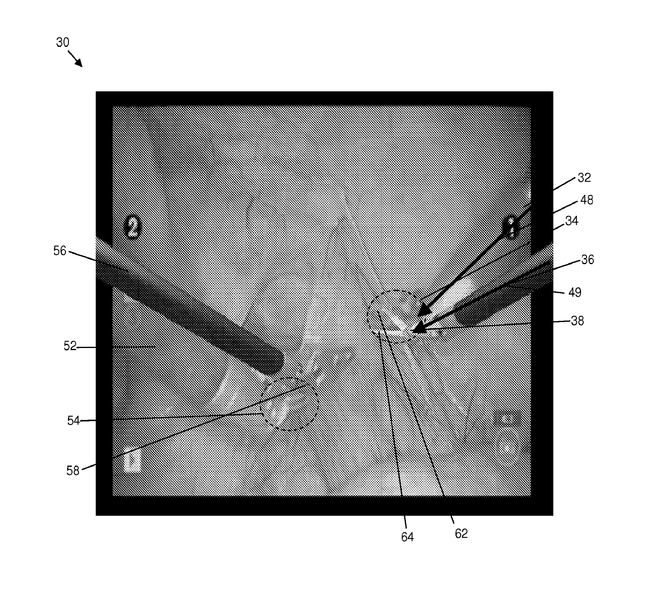
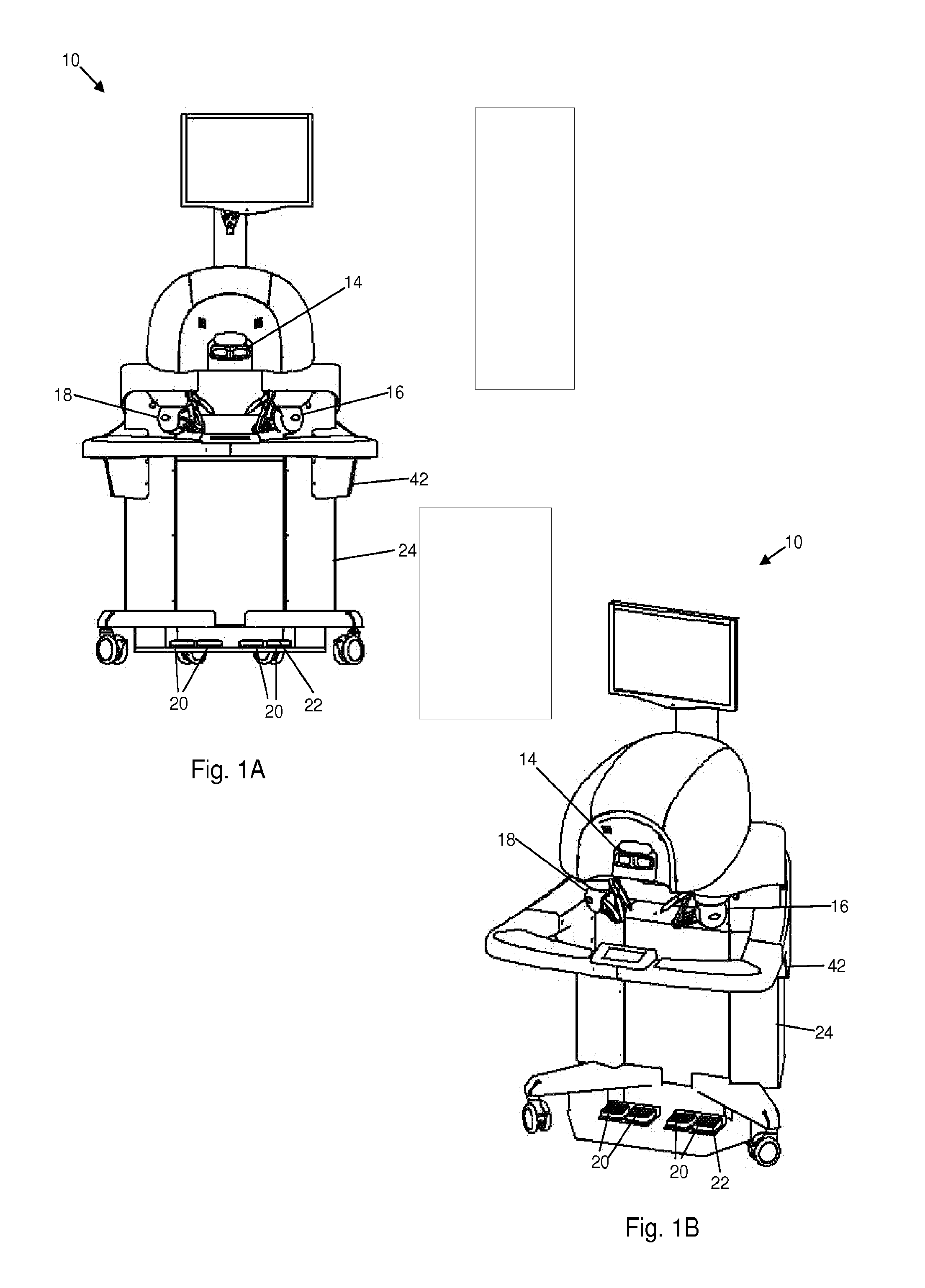
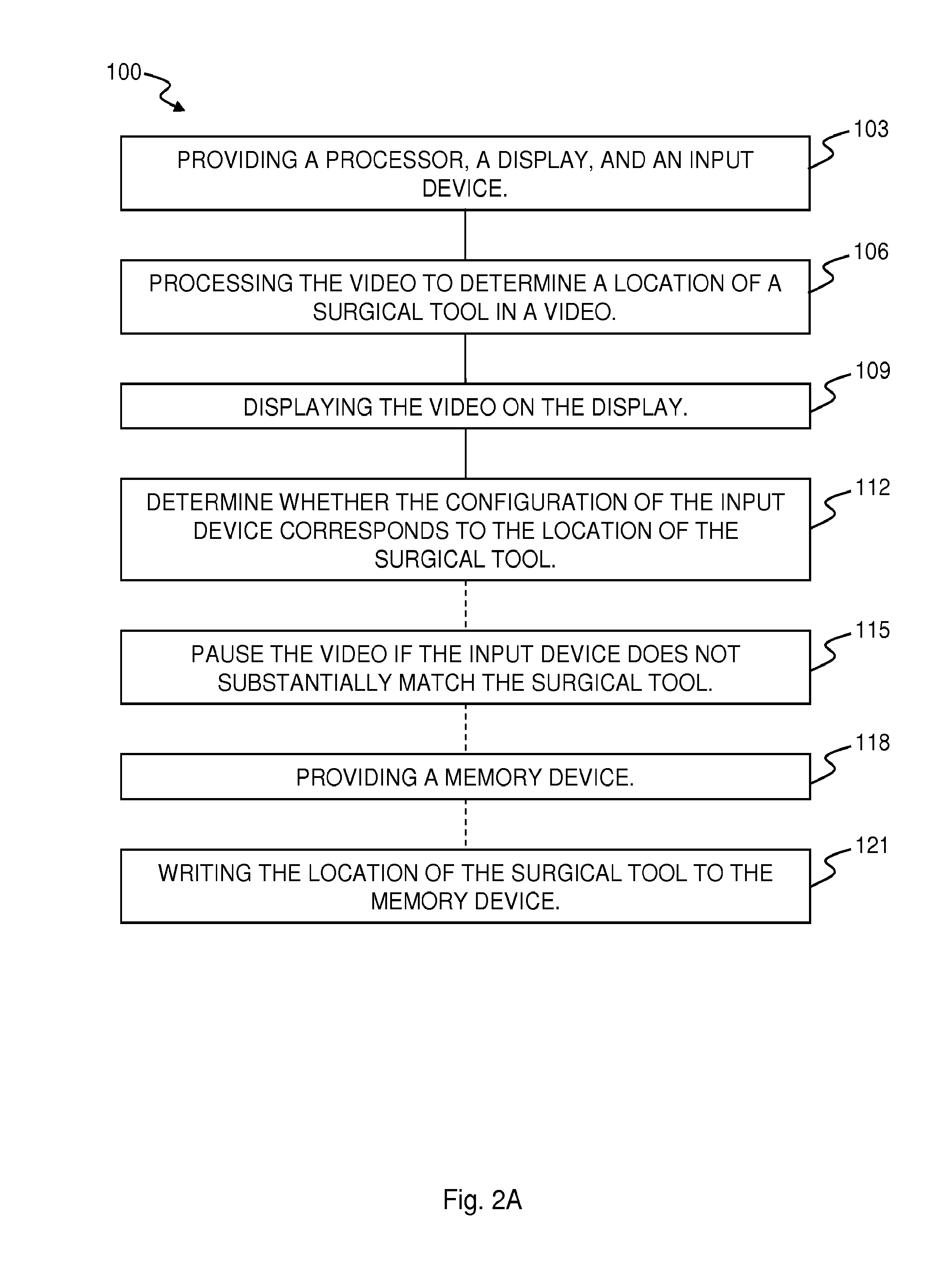
The present invention may be embodied as a method of minimally-invasive surgery (“MIS”) training using a video of an MIS comprising the steps of providing a processor, a display, and a first input device. The method comprises the step of processing the video using the processor to determine a location of the first surgical tool in each of the frames, determining whether the configuration of the first input device substantially corresponds to the location of the first surgical tool in each frame of the video while the video is displayed. The present invention may be embodied as a system for MIS training. The system comprises a processor, a communication device, and a first input device in communication with the processor. The processor is programmed perform any or all of the described disclosed methods.

Description

CROSS-REFERENCE TO RELATED APPLICATION[0001]This application claims the benefit of priority to U.S. provisional patent application Ser. No. 61 / 348,733, filed May 26, 2010, now pending, the disclosure of which is incorporated herein by reference.FIELD OF THE INVENTION[0002]The invention relates to surgical training, and more particularly to training a person in performing minimally-invasive surgical procedures.BACKGROUND OF THE INVENTION[0003]Minimally invasive surgery (“MIS”) has been accepted as a useful alternative to open surgery for many health conditions. While safer for the patient, MIS poses a number of unique challenges to the surgeon performing them. The challenges fall into two broad domains: (i) the cognitive domain, wherein the surgeon uses knowledge and prior experience to make decisions regarding the procedure; and (ii) the motor control domain, where the surgeon uses physical skills to carry out specific decisions made through their cognitive process. For example, in ...

Claims


Application Information

Patent Timeline
Patent Type & Authority Applications(United States)
IPC IPC(8): G09B5/02G09B23/28
CPCG09B5/02G09B23/28G09B23/285G16H20/40
Inventor KESAVADAS, THENKURUSSIGURU, KHURSHID
Owner HEALTH RES INC
Why Eureka
Try Eureka