
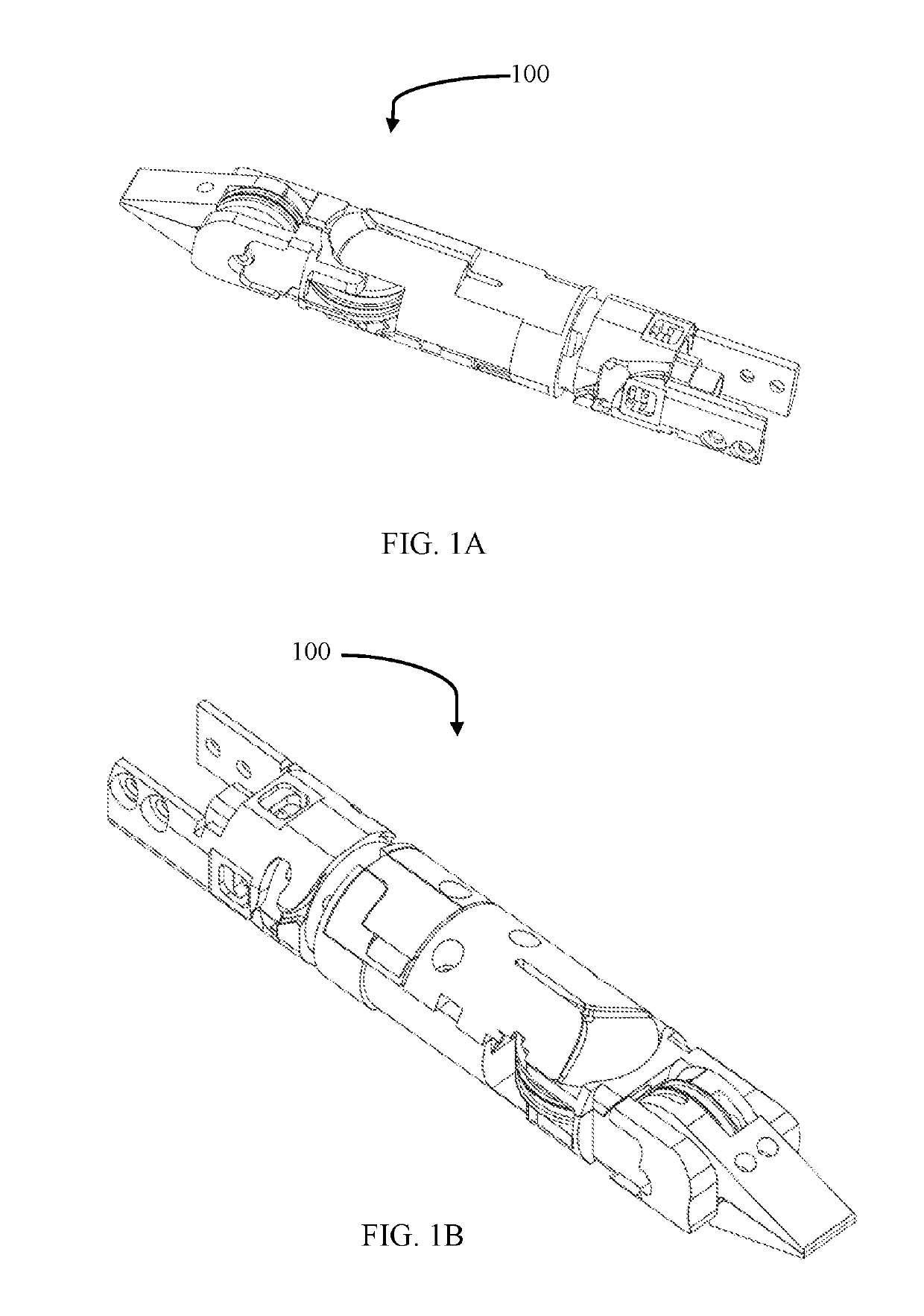
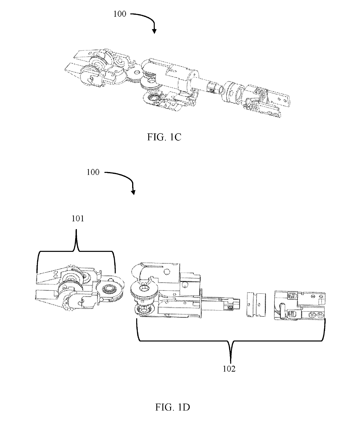
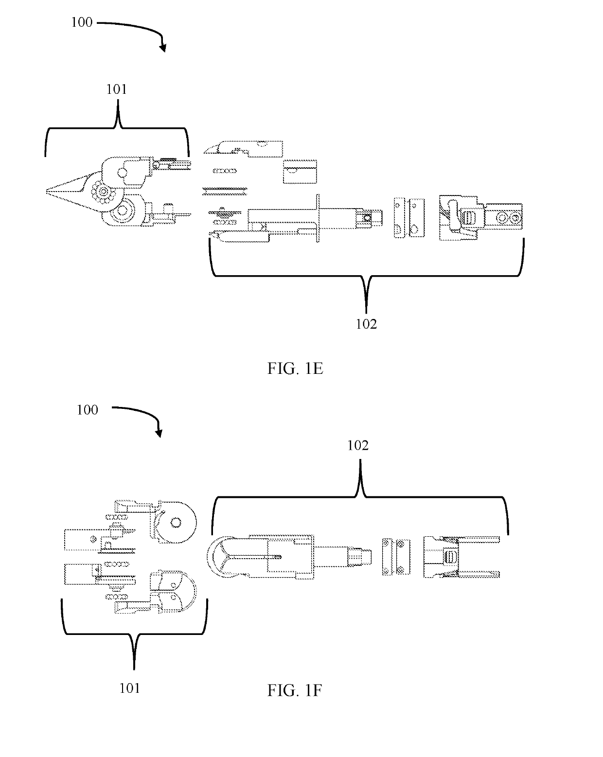
Virtual reality wrist assembly

a wrist assembly and virtual reality technology, applied in the field of minimally invasive surgery, minimally invasive surgical tools and endeffectors and virtual reality minimally invasive surgical systems, can solve the problems of affecting the efficiency of a wrist assembly, and restricting the movement of said wrist assembly, so as to reduce torque

Active Publication Date: 2019-05-16
VICARIOUS SURGICAL INC
View PDF0 Cites 22 Cited by
  • Summary
  • Abstract
  • Description
  • Claims
  • Application Information

AI Technical Summary

Benefits of technology

The technology described in this patent allows for the rotation of a jaw in two directions. The first actuation hub has a second cable routing protrusion that helps the second cable move along during rotation of the jaw in the opposite direction. This reduces torque and prevents damage to the cable during rotation. The second cable routing protrusion also helps maintain the length of the cable during rotation. This technology improves the performance and durability of the jaw.

Problems solved by technology

Alternatively, other wrist assemblies utilize a plurality of pulleys and cables per each degree of freedom, resulting in complex and cumbersome assemblies with limited ranges of motion.
The amount of cables required for three degrees of freedom can impact the efficiency of a wrist assembly, as well as restrict the movement of said wrist assembly.
The use of multiple cables per one degree of freedom creates inherent complications in wrist assemblies of surgical robotic systems.
Generally, robotic arms contain multiple degrees of freedom, however the number of degrees of freedom are restricted due to the size of the arms, as well as are confined in movement due to the boundaries of the work space inside a patient.
The size constraints of robotic arms of surgical robotic systems impact the number of cables that can be routed from the drive assembly through the arms and to a wrist assembly, thus limiting the number of degrees of freedom attainable by the system.

Method used


Image

  • Virtual reality wrist assembly
  • Virtual reality wrist assembly
  • Virtual reality wrist assembly

Examples


Embodiment Construction

[0132]While the present system is designed for use by a surgeon within the abdominal cavity, many alternative uses of the device are possible. For example, a user might be a physician's assistant, nurse, surgical aid, or any other surgical personnel. Additionally, the device could be disposed within any part of a patient's body, and future embodiments could be designed to be much smaller so as to allow for use within smaller areas of a patient's body. Both smaller and larger devices can be fabricated for uses in areas such as the paranasal sinuses, colon, stomach, or any other areas within the human body including but not limited to, the abdomen, cranium and cervicis. Micro-fabrication using MEMS or other means could allow for a device to be positionable within immensely small areas such as human blood vessels.

[0133]In some embodiments, the device may be used for non-surgical or non-medical tasks such as bomb diffusion, military reconnaissance, inspectional services, or any other ta...


PUM


Abstract

A surgical apparatus system for minimally invasive surgery (MIS) which includes a wrist assembly. The wrist assembly includes a first jaw, a first actuation hub, and a cable redirecting hub operably coupled to the first actuation hub, a second jaw, a second actuation hub, a housing for the first and second jaws, a first cable, a second cable, a third cable, rotational position sensors, and a control system. The first and second jaws of the wrist assembly are movably opposed, and the cables are configured such that applying tensions upon them cables produces rotation about a jaw axis. The wrist assembly may further include a hinge-rotary assembly to configured to provide rotation about a pitch axis and / or a roll axis. The wrist assembly may further include a fourth cable configured such that applying tensions upon the fourth cable and the opposing cable produces rotation about a pitch axis.

Description

CROSS-REFERENCES TO RELATED APPLICATIONS[0001]This application claims the benefit under 35 U.S.C. § 119(e) to U.S. Provisional Patent Application No. 62 / 585,277, entitled “Virtual Reality Wrist Assembly,” filed on Nov. 13, 2017, which is hereby incorporated by reference in its entirety.BACKGROUNDField of Invention[0002]This application generally relates to minimally invasive surgery, minimally invasive surgical tools and end-effectors and virtual reality minimally invasive surgical systems.Description of Related Art[0003]The field of minimally invasive surgery has undergone tremendous development and growth since its inception in the 1900's, with said developments and growth yielding improved results for patients. One of the major developments in the minimally invasive surgery field has been the implementation of surgical robotic devices. The implementation and utilization of surgical robotic devices in the minimally invasive surgery field has led to an increase in the number and ty...

Claims


Application Information

Patent Timeline
Patent Type & Authority Applications(United States)
IPC IPC(8): A61B34/30A61B17/00
CPCA61B34/30A61B17/00234A61B2034/306A61B17/29A61B90/06A61B34/71A61B34/10A61B2017/2901A61B2017/2926A61B2017/2932A61B2017/2947A61B2034/305A61B2034/301A61B2034/302A61B2017/00367A61B2017/00477A61B2034/101A61B2090/035A61B2034/2059
Inventor WENTWORTH, MARSHALLKLINE, ERICEILENBERG, MICHAELKHALIFA, SAMMY
Owner VICARIOUS SURGICAL INC
Learn More