
Vascular bands and delivery systems therefor

a technology of vascular bands and vascular bands, which is applied in the field of delivery tools and implantable vascular bands, can solve the problems of loss of blood through rupture and death, high mortality, and substantial stress on the body

Inactive Publication Date: 2013-10-31
ENDOSPAN
View PDF8 Cites 26 Cited by
  • Summary
  • Abstract
  • Description
  • Claims
  • Application Information

AI Technical Summary

Benefits of technology

This patent describes a device that can be used to treat certain medical conditions. When the device is in a certain state, a special element can be used to secure the device in place. Once the device is in its normal, relaxed state, the element can be removed, allowing the device to return to its original state. This makes it easier to remove and use the device for its intended purpose.

Problems solved by technology

Left untreated, the aneurysm will frequently rupture, resulting in loss of blood through the rupture and death.
Aortic aneurysms are the most common form of arterial aneurysm and are life-threatening.
Aneurysms in the abdominal aorta are associated with particularly high mortality; accordingly, current medical standards call for urgent operative repair when aneurysm diameter is larger than 5 cm.
Abdominal surgery, however, results in substantial stress to the body.
Although the mortality rate for an aortic aneurysm is extremely high, there is also considerable mortality and morbidity associated with open surgical intervention to repair an aortic aneurysm.
However, when an aneurysm is located near the iliac arteries, there may be an ill-defined neck or no neck below the aneurysm.
Such an ill-defined neck may provide insufficient healthy aortic tissue to which to successfully mount a stent-graft.
Furthermore, much of the abdominal aorta wall may be calcified which may make it difficult to attach the stent-graft to the aortic wall.
A short or absent infrarenal neck, large aortic diameters, and excessive angulation at this level are the main problems.

Method used


Image

  • Vascular bands and delivery systems therefor
  • Vascular bands and delivery systems therefor
  • Vascular bands and delivery systems therefor

Examples


Embodiment Construction

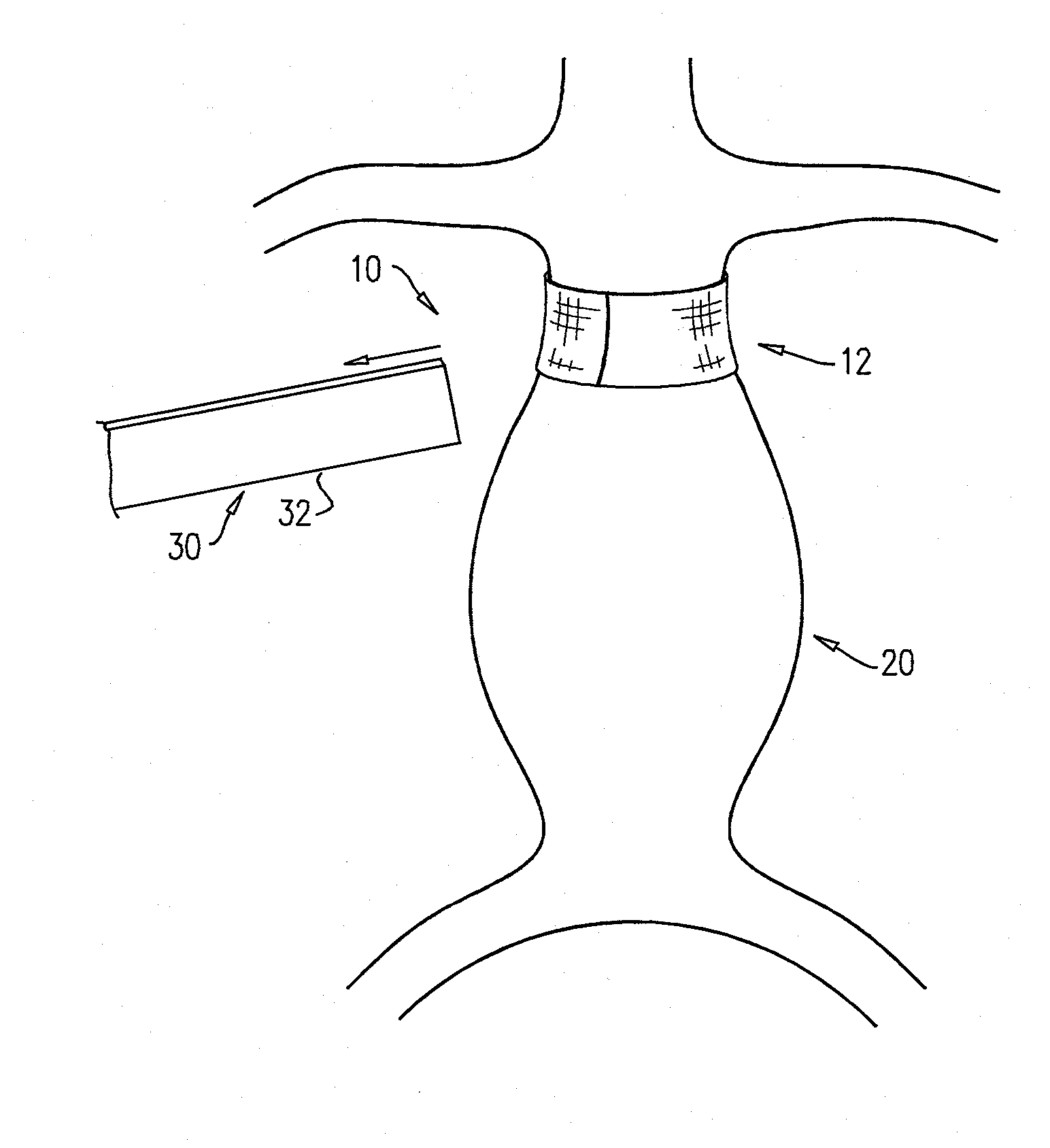
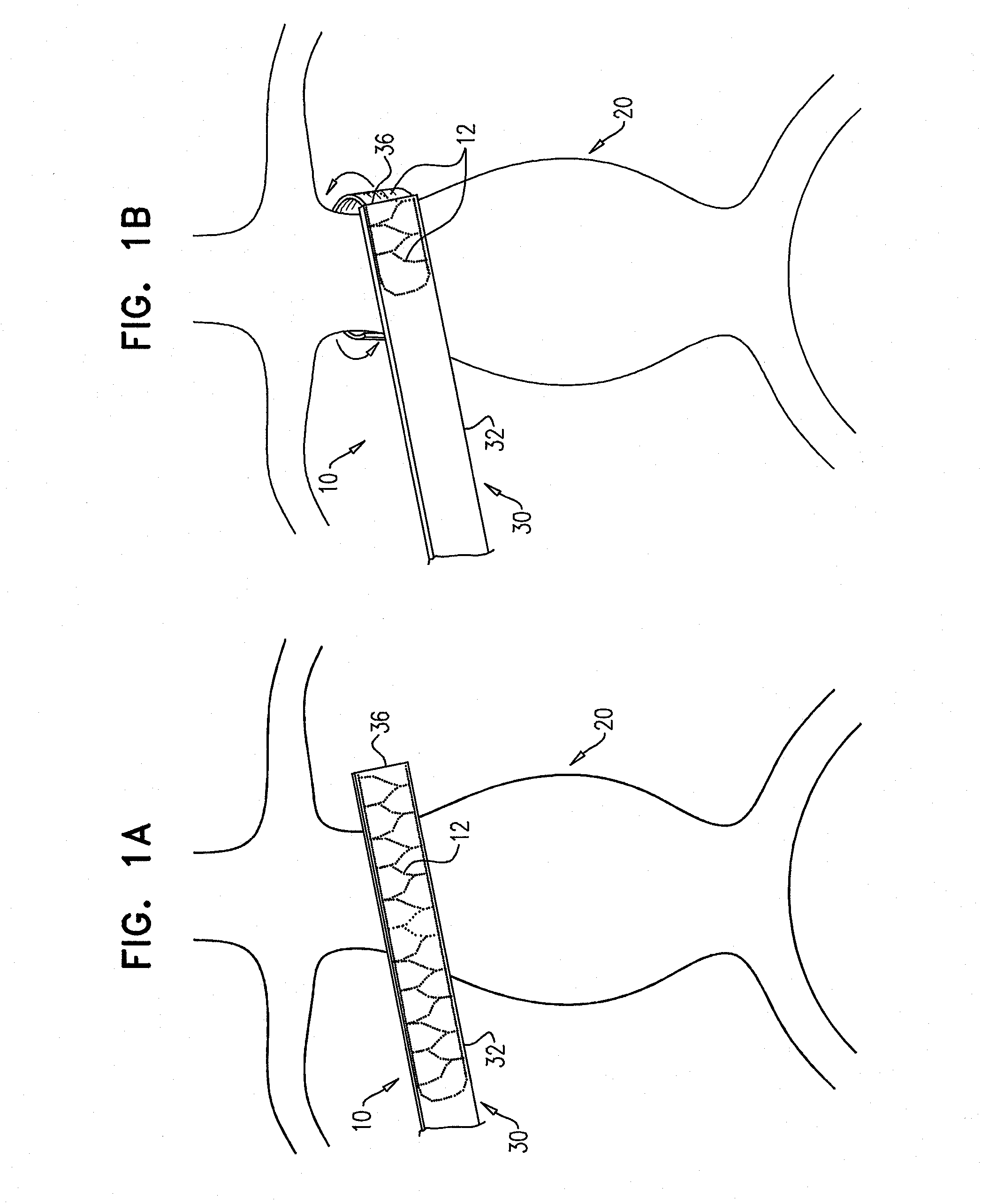
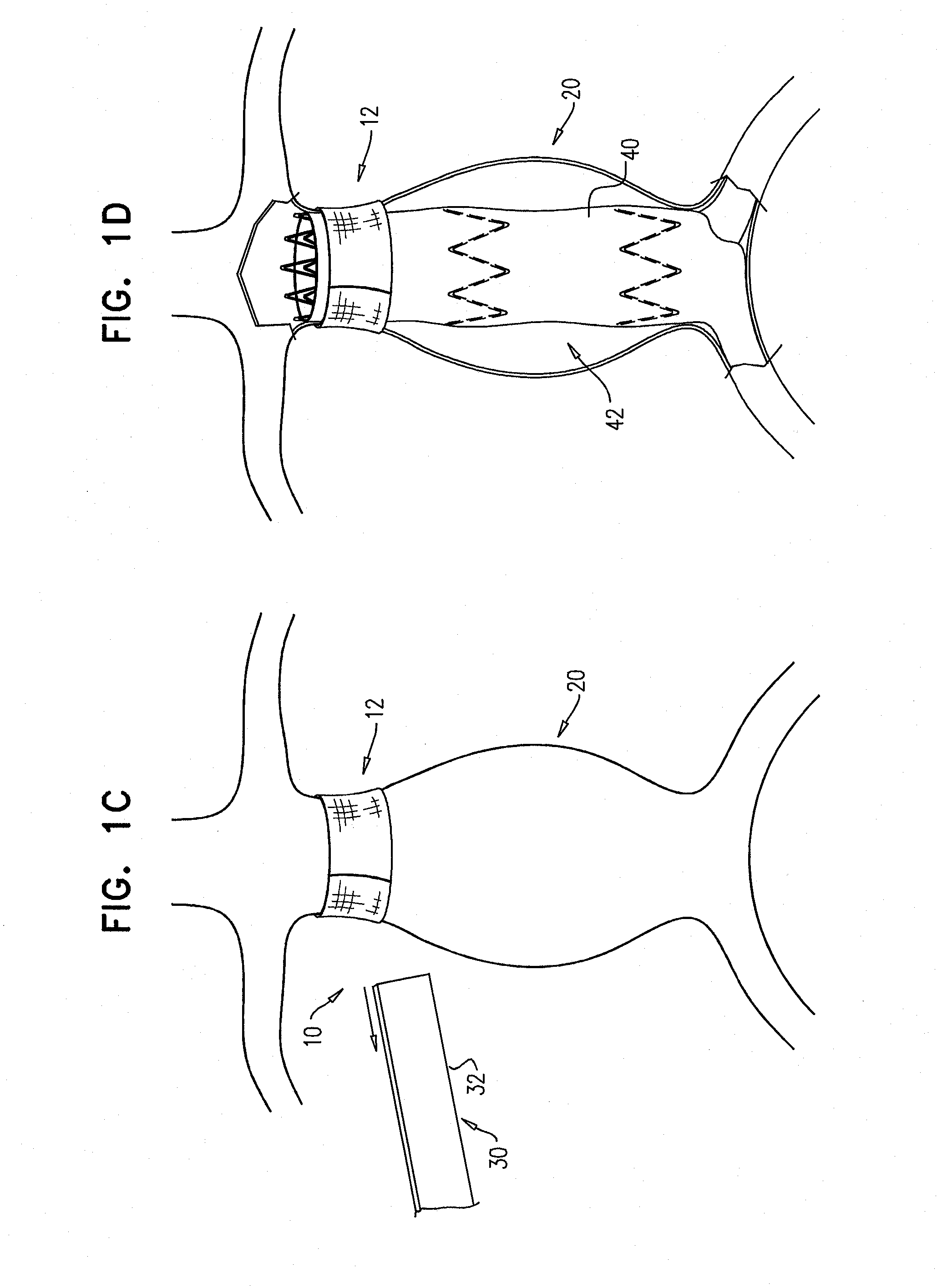
[0076]FIGS. 1A-D are schematic illustrations of a delivery system 10 for delivering a medical device 12 around an aorta 20, in accordance with an application of the present invention. Delivery system 10 may be used for delivering medical device 12 around aorta 20 (as shown) or other tissue, such as an organ, e.g., as a tubular organ, e.g., another blood vessel or a nerve. Delivery system 10 comprises a catheter 30, which comprises an outer pull-back shaft 32 having generally rectangular cross sections. Medical device 12 is initially removably disposed within outer pull-back shaft 32, with the medical device in a deformed generally planar state, as shown in FIG. 1A. For some applications, medical device 12 comprises an extra-luminal ring, such as shown in FIGS. 1A-D. For some of these applications, the ring is generally planar and rectangular when deformed for delivery.

[0077]During a first stage of an implantation procedure performed using delivery system 10, a surgeon creates a work...


PUM


Abstract

An extra-luminal ring (1200) includes a structural member (1202), which assumes a first elongate hollow shape (1206) when in a relaxed state; when deformed to a planar state (1208), generally defines a planar shape (1209) having two first sides (1220A, 1220B) parallel to each other, and two second sides (1222A, 1222B) parallel to each other; and when in the relaxed state, is configured such that the two first sides (1220A, 1220B) are generally straight and parallel with each other, and the two second sides (1222A, 1222B) are curved at least partially around a first longitudinal axis (1230) defined by the first elongate hollow shape (1206). The structural member (1202), when in a deformed state, has a second elongate hollow shape (1240), different from the first elongate hollow shape (1206), in which the two second sides (1222A, 1222B) are generally straight and parallel with each other, and the two first sides (1220A, 1220B) are curved at least partially around a second longitudinal axis (1250) defined by the second elongate hollow shape (1240).

Description

CROSS-REFERENCE TO RELATED APPLICATIONS[0001]The present patent application claims priority from U.S. Provisional Application 61 / 443,740, filed Feb. 17, 2011, which is assigned to the assignee of the present application and is incorporated herein by reference.FIELD OF THE APPLICATION[0002]The present invention relates generally to implantable medical devices, and specifically to delivery tools and implantable vascular bands.BACKGROUND OF THE APPLICATION[0003]An aneurysm is a localized, blood-filled dilation (bulge) of a blood vessel caused by disease or weakening of the vessel wall. Left untreated, the aneurysm will frequently rupture, resulting in loss of blood through the rupture and death. Aneurysms are commonly classified by shape, structure and location. Aortic aneurysms are the most common form of arterial aneurysm and are life-threatening. It is common for an aortic aneurysm to occur in the portion of the abdominal aorta between the renal arteries and the iliac arteries. Aneu...

Claims


Application Information

Patent Timeline
Patent Type & Authority Applications(United States)
IPC IPC(8): A61B17/12A61F2/06A61F2/07
CPCA61B17/12022A61F2/07A61F2002/065A61B17/12A61F2/89
Inventor SHALEV, ALON
Owner ENDOSPAN
Learn More