
Vehicle speed limiter via gauge interface

a technology of electronic control unit and vehicle, applied in vehicle position/course/altitude control, process and machine control, instruments, etc., can solve the problems of complex operation of vehicle electronic control unit, unsafe vehicle, inoperable vehicle, etc., and achieve enhanced electronic control unit and limit the operation of the vehicle

Active Publication Date: 2013-10-31
ARCTIC CAT
View PDF9 Cites 9 Cited by
  • Summary
  • Abstract
  • Description
  • Claims
  • Application Information

AI Technical Summary

Benefits of technology

The present invention is an electronic control unit for a vehicle that can limit its operation based on a user-specified speed limit. This is done without the need to reprogram the control unit that uses lookup tables or maps to determine its operational parameters. The electronic control unit can also limit the operation of the vehicle based on safety factors, such as the identity of the driver or passenger or the use of safety equipment, such as seat belts. The technical effect of this invention is to allow for safer and more efficient operation of vehicles without the need for reprogramming or complex safety equipment.

Problems solved by technology

Reprogramming a vehicle ECU is a complex operation, requiring special purpose software, hardware, connectors, and the like.
If reprogramming is performed incorrectly, the vehicle may become inoperable or unsafe.

Method used


Image

  • Vehicle speed limiter via gauge interface
  • Vehicle speed limiter via gauge interface
  • Vehicle speed limiter via gauge interface

Examples


first embodiment

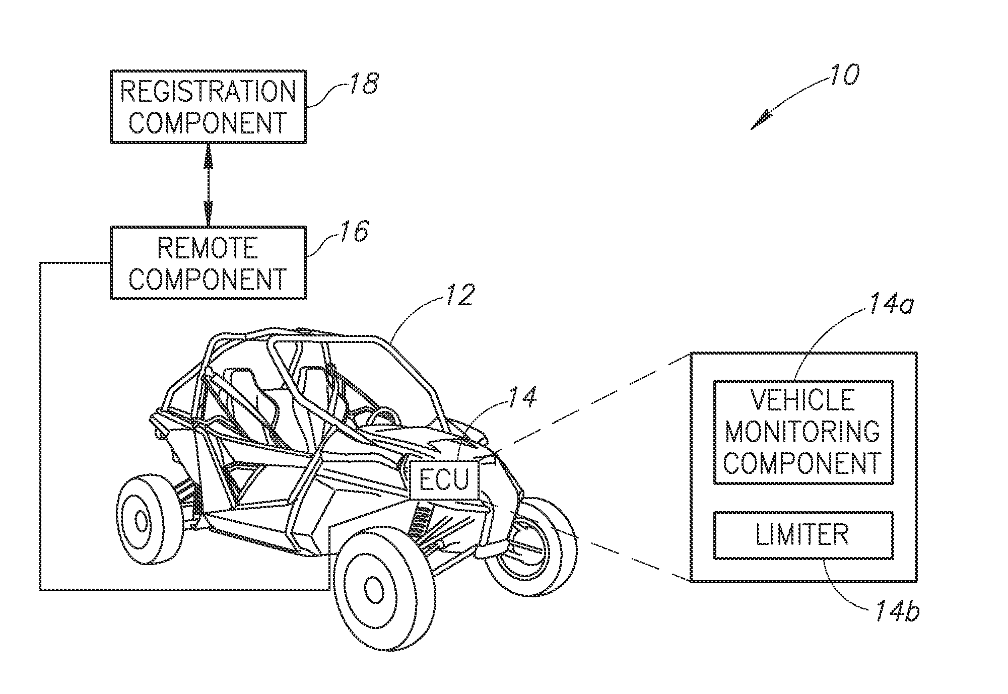
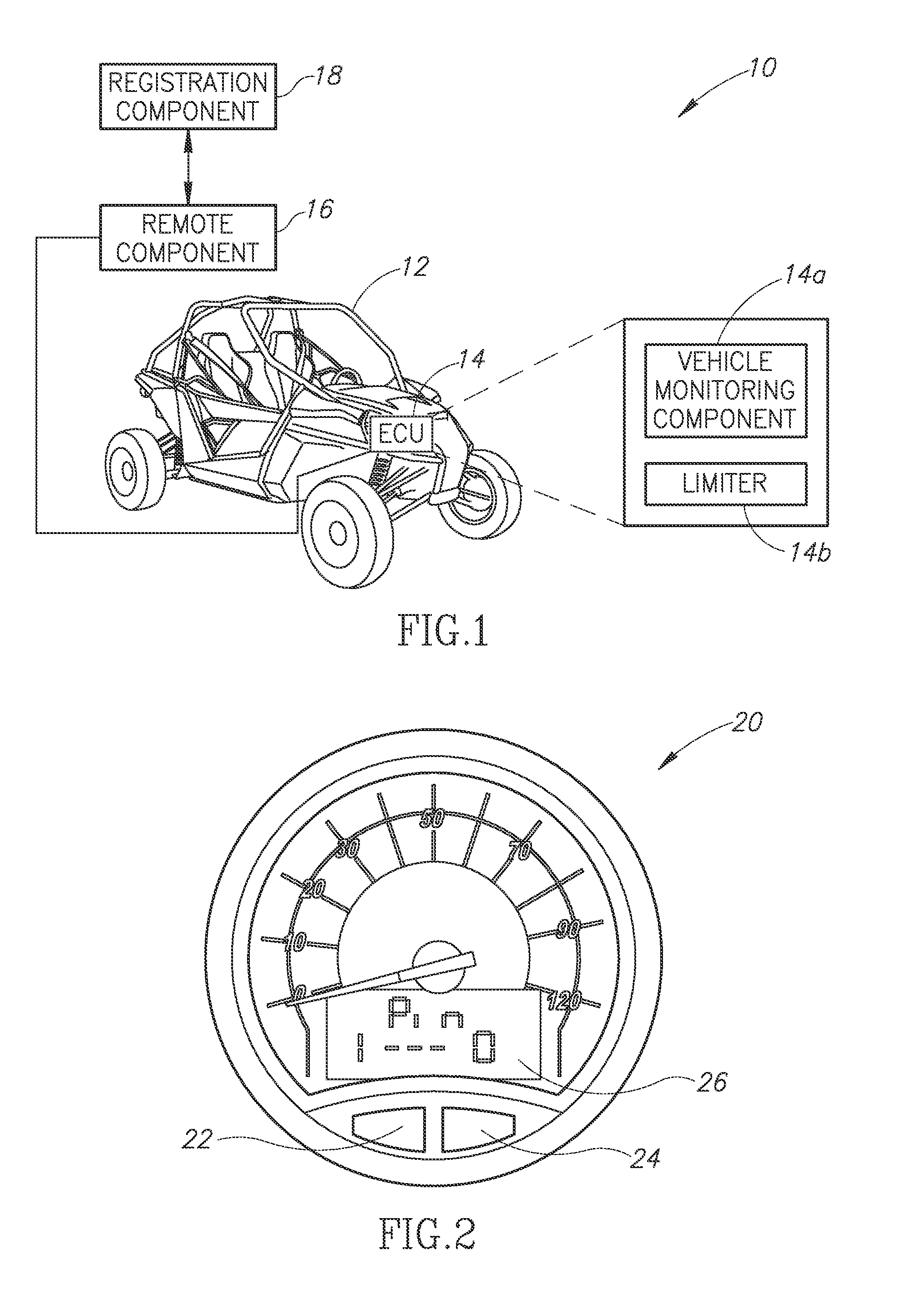
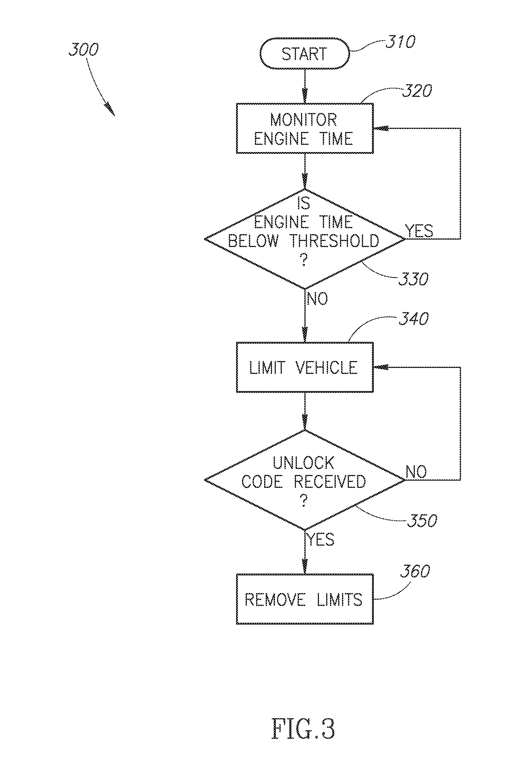
[0019]In a first embodiment, described with respect to FIGS. 1-3 below, the ECU can monitor a vehicle parameter, such as engine operation time, fuel consumption, speed, or distance travelled, and if the parameter exceeds a certain limit, the vehicle is permitted to operate only in a limited capacity. In one embodiment, the ECU will continue to limit the operation of the vehicle until an unlocking code is entered. For example, a vehicle can be operated by a dealer and by potential customers for a certain time (e.g., 5 engine hours) before the ECU initiates operation limits. After reaching the prescribed parameter limit, the ECU limits operation of the vehicle to within certain prescribed parameters, such as by limiting the engine speed (RPM) or the ground speed of the vehicle, or any other suitable parameter.

[0020]In another embodiment, described with respect to FIGS. 4-7 below, the ECU is configured to receive limit data, such as a maximum speed, that is entered by a user via an inp...

second embodiment

[0031]FIG. 4 is a schematic diagram illustrating an ROV having an electronic vehicle limiter system according to the present invention. In particular, FIG. 4 depicts an ECU system 10′ that is similar to the system 10 described with respect to FIG. 1. The illustrated system 10′ includes a vehicle 12 and an ECU 14. The ECU 14 includes a vehicle-monitoring component 14a and a limiter 14b. The vehicle 12, ECU 14, monitoring component 14a, and limiter 14b are described with respect to FIG. 1.

[0032]The system 10′ differs from the system 10 of FIG. 1 primarily in that the ECU 14 is in communication with an input device 30 rather than the remote component 16. In addition, system 10′ does not necessarily include the registration component 18, although in other alternate embodiments the system 10′ may be in communication with other systems or devices. The input device 30 may be any device that is configured to receive limit data from a user or other source, and to communicate that limit data ...


PUM


Abstract

An electronic control unit (“ECU”) limiter is disclosed. The electronic control unit may be configured to receive a user-specified vehicle limit, such as a speed limit, from an input device, such as a gauge interface of the vehicle or a diagnostic tool. The electronic control unit is further configured to enforce the received vehicle limit, without a need to reprogram (e.g., erase and rewrite) vehicle engine control data stored by the electronic control unit, such as lookup tables or maps that are used to determine the operational parameters (e.g., ignition timing, throttle) based on sensor inputs (e.g., engine revolutions per minute, engine temperature).

Description

PRIORITY CLAIM[0001]This application is a continuation-in-part of U.S. patent application Ser. No. 13 / 460,588, filed Apr. 30, 2012, the contents of which are incorporated herein by reference in their entirety.FIELD OF INVENTION[0002]This invention relates generally to a vehicle electronic control unit (“ECU”) limiter that is configurable via a gauge interface or other input device, such as a diagnostic tool, without needing to reprogram the ECU.BACKGROUND OF THE INVENTION[0003]Recreational vehicles, such as all-terrain vehicles (“ATVs”), recreational off-road vehicles (“ROVs”), and other similar equipment usually represent a significant purchase. As such, buyers enjoy testing a vehicle before purchasing in an environment similar to the one in which they will use the vehicle. The buyer may wish to test the vehicle under actual conditions such as at full throttle, full speed, etc. However, the dealer, manufacturer, and consumer have an interest in selling the vehicle and having it reg...

Claims


Application Information

Patent Timeline
Patent Type & Authority Applications(United States)
IPC IPC(8): G06F17/00
CPCG06F17/00B60W30/146B60W10/06B60K2031/0091B60W2050/0005B60W2556/45B60W2050/0075
Inventor JOHNSON, DANIELJANISCH, DARREL
Owner ARCTIC CAT
Learn More