
Internal combustion engine with exhaust aftertreatment and its method of operation

Active Publication Date: 2013-10-31
HONDA MOTOR CO LTD +1
View PDF7 Cites 31 Cited by
  • Summary
  • Abstract
  • Description
  • Claims
  • Application Information

AI Technical Summary

Benefits of technology

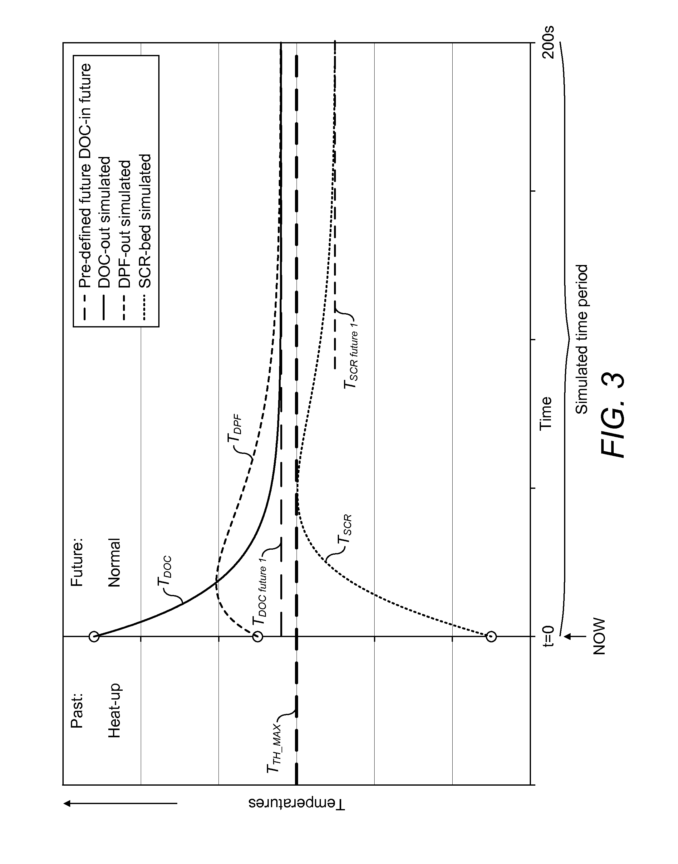
The present invention is about a method for operating an internal combustion engine with an exhaust system that includes first and second exhaust aftertreatment means. The method involves controlling engine operation in a normal mode or a heat-up mode. The invention takes into account the current conditions and the thermal inertia of the exhaust system to predict the temperature of the second exhaust aftertreatment means in a simulated time period. The predicted temperature is compared to an upper temperature threshold to stop the heat-up mode and switch to normal mode. The method helps to optimize the thermal control of the exhaust system and improve emissions control and fuel efficiency.

Problems solved by technology

Compression ignition (i.e., diesel) engines, however, are typically equipped with two-way catalytic converters (also referred to as Diesel Oxidation Catalyst—DOC), which may not efficiently reduce nitrogen oxides (NOx).
One of the challenges in such exhaust line with serially mounted exhaust aftertreatment devices is its thermal management.
In addition, each component in the exhaust line has a thermal inertia, whereby the temperature increase of components situated further away from the engine is delayed as compared to those near the engine.
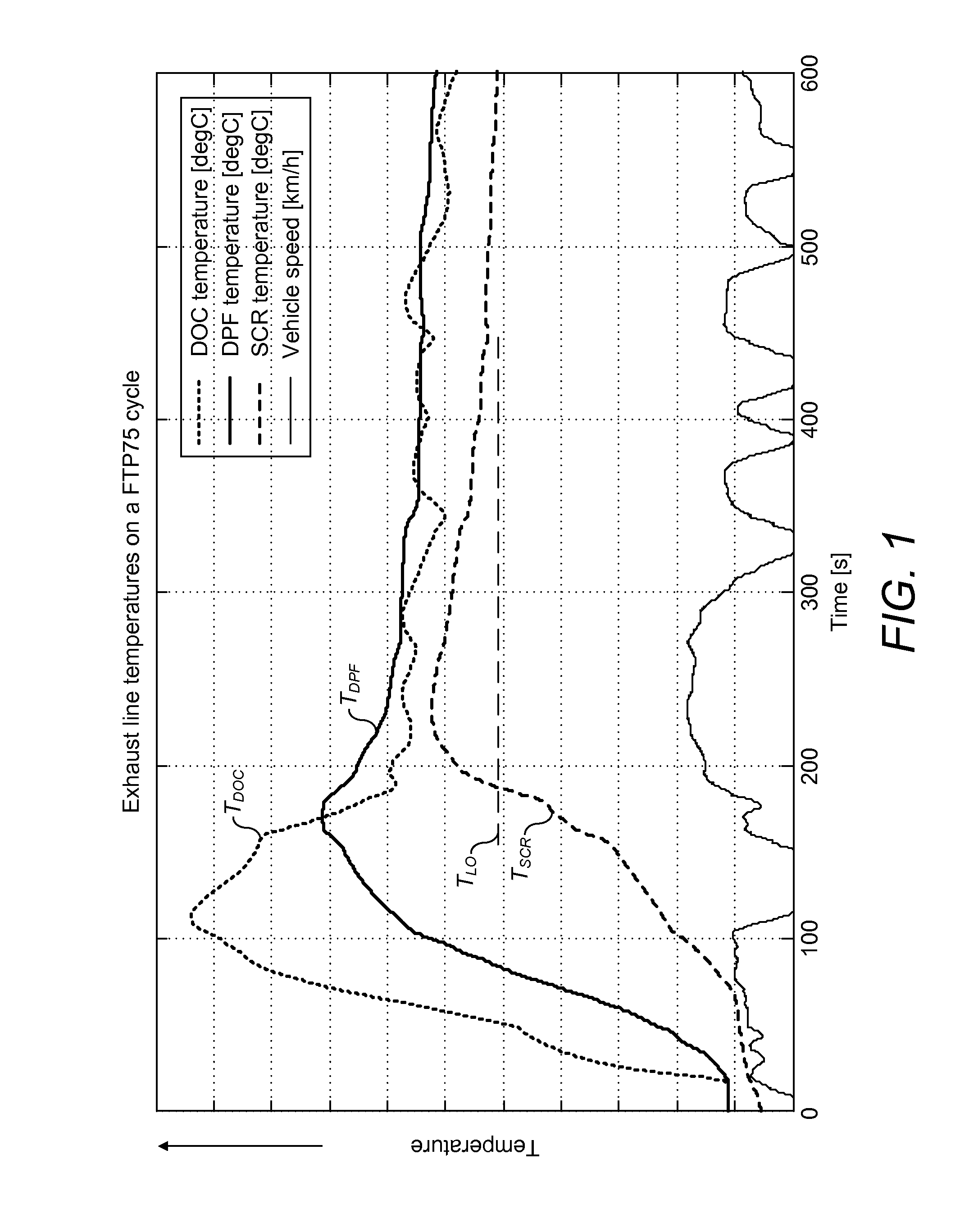
Unfortunately, under such control conditions the DOC gets very hot, while at the same time the SCR is still relatively cool due to thermal inertia of the components in the exhaust line.

Method used


Image

  • Internal combustion engine with exhaust aftertreatment and its method of operation
  • Internal combustion engine with exhaust aftertreatment and its method of operation
  • Internal combustion engine with exhaust aftertreatment and its method of operation

Examples


Embodiment Construction

[0033]As explained with reference to FIG. 1 hereinabove, a simple temperature-based control of the SCR catalyst heat-up mode, wherein heating is stopped when it is measured that the SCR catalyst has reached its light off temperature, is not optimal since it typically leads to a temperature overshoot. This effect, due to the thermal inertia of the components in the exhaust line, implies excessive fuel consumption, while the higher temperature of the SCR catalyst is not even useful in terms of NOx conversion.

[0034]The present invention provides an optimized thermal control of exhaust aftertreatment means such as e.g. an SCR-catalyst in an engine exhaust line, wherein the SCR is located downstream of first exhaust aftertreatment means.

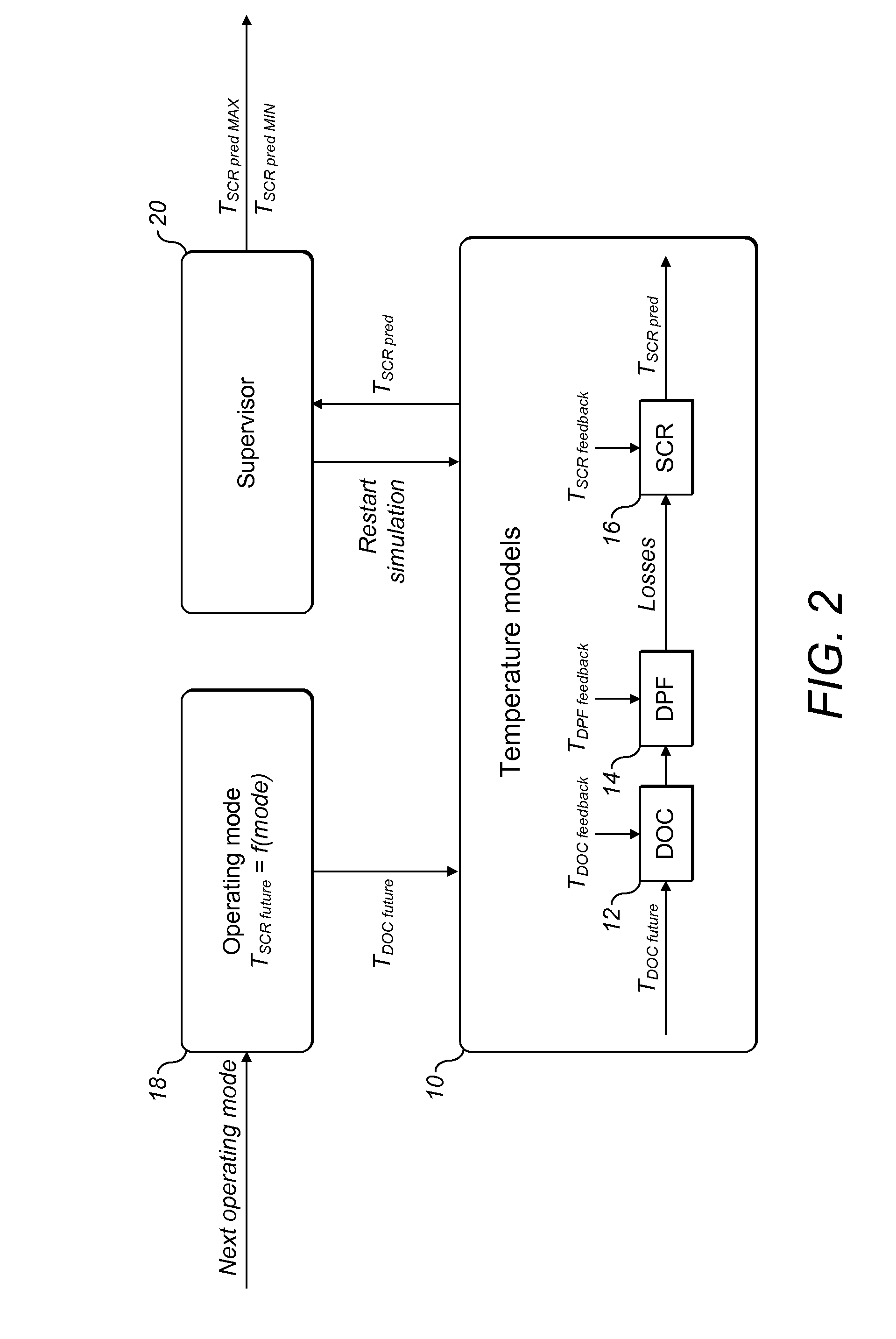
[0035]A preferred embodiment of this method will now be described with respect to FIGS. 2 to 5 as applied to a diesel internal combustion engine comprising an exhaust line with first exhaust aftertreatment means comprising a diesel oxidation catalyst (DOC...


PUM


Abstract

A method of operating an internal combustion engine is proposed, the engine comprising an exhaust system with a DOC and a DPF and, downstream thereof a SCR catalyst. The ECU is configured to allow operation in at least one of a normal mode and a heat-up mode. A predicted temperature evolution of said second exhaust after treatment means is regularly determined based on a thermal model taking into account the thermal inertia of the exhaust system and having as input the current temperatures of the DOC / DPF and SCR. The predicted temperature evolution of SCR is indicative of the temperature that the SCR may reach during a simulated time period in case the operating mode. The engine operating mode is changed depending on the predicted temperature evolution.

Description

CROSS REFERENCE TO RELATED APPLICATIONS[0001]This application is a national stage application under 35 U.S.C. 371 of PCT Application No. PCT / EP2011 / 050158 having an international filing date of 7 Jan. 2011, the entire disclosure of which is hereby incorporated herein by reference.FIELD OF THE INVENTION[0002]The present invention generally relates to internal combustion engines equipped with exhaust aftertreatment devices. It more specifically relates to the control of an engine equipped with an oxidation catalyst and a NOx treatment device such as a SCR catalyst.BACKGROUND OF THE INVENTION[0003]Current emission control regulations necessitate the use of exhaust aftertreatment systems in order to reduce the concentration of combustion byproducts and / or products of incomplete combustion.[0004]Spark ignition (i.e., gasoline) engines conventionally use three-way catalytic converters to satisfy emissions regulations. Compression ignition (i.e., diesel) engines, however, are typically equ...

Claims


Application Information

Patent Timeline
IPC IPC(8): F01N9/00
CPCF01N9/00F01N11/005F02D41/024Y02T10/12
Inventor SCHMITT, JULIENPARMENTIER, MICHAEL
Owner HONDA MOTOR CO LTD
Learn More