Organic electroluminescent device

a technology of electroluminescent devices and electroluminescent tubes, which is applied in the manufacture of electrode systems, electric discharge tubes/lamps, and discharge tubes luminescent screens, etc., can solve the problems of oled devices that lose light, the loss factor of oled devices is particularly difficult to extract light in an economic way, and the light emitted in these modes is particularly difficult to be extracted. , to achieve the effect of low cost and easy manufacturing and reliabl

Inactive Publication Date: 2013-11-07
OLEDWORKS GMBH
View PDF9 Cites 4 Cited by
  • Summary
  • Abstract
  • Description
  • Claims
  • Application Information

AI Technical Summary

Benefits of technology

[0005]It is an object of the invention to provide an OLED device with improved

Problems solved by technology

However, the mount of light emitted from the OLED devices is only 20% of the amount of light internally generated by the light emitting layer.
The major loss factor in OLED devices is trapping of the light due to the flat geometry of the OLED device.
So far, the light trapped in these modes was particularly difficult to be extracted in an economic way.
Structured substrates will additionally increase the manufacturing effort and the ma

Method used


Image

  • Organic electroluminescent device
  • Organic electroluminescent device
  • Organic electroluminescent device

Examples


example a

[0030]

Layermateriald (nm)Tg (° C.)Substrate 1glassnon-organicFirst electrode 2ITO100non-organicOLE layer stack 3Spiro-TAD:F4-TCNQ 2%30133Spiro-TAD10133Spiro.TAD:Ir(mdq)2 acac301339%Bis-OXD10147Bis-OXD:W2(hpp)4 5%10147Protection layer 41WO360non-organicBuckling layer 42α-NPD:F4-TCNQ25 95Stress inducingAl20non-organiclayerCDL (optional)Al (or Co)80non-organic

[0031]In example A, Tg of the buckling layer is 38° C. lower than the lowest Tg of the organic-light-emitting layer stack.

example b

[0032]

Layermateriald (nm)Tg (° C.)Substrate 1glassnon-organicFirst electrode 2ITO100non-organicOLE layer stack 3Spiro-TAD:F4-TCNQ 2%30133Spiro-TAD10133Spiro.TAD:Ir(mdq)2 acac301339%Bis-OXD10147Bis-OXD:W2(hpp)4 5%10147Protection layer 41WO360non-organicBuckling layer 42TPD:F4-TCNQ25 60Stress inducingAl20non-organiclayerCDL (optional)Al (or Co)80non-organic

[0033]In this example B, Tg of the buckling layer is 73° C. lower than the lowest Tg of the organic-light-emitting layer stack.

[0034]In the examples A and B, Bis-OXD denotes 4,4′-bis(5-phenyl-[1,3,4]oxadiazol-2-yl)-2,2′-dinaphthylbiphenyl and (hpp) denotes the anion of 1,3,4,6,7,8-hexahydro-2H-pyrimido[1,2-c]pyrimidine. As an alternative for the protection layer, MoO3 or V2O5 could be used in these examples instead of WO3

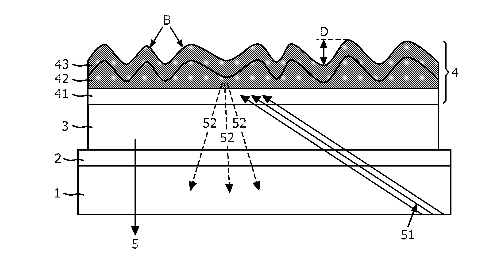
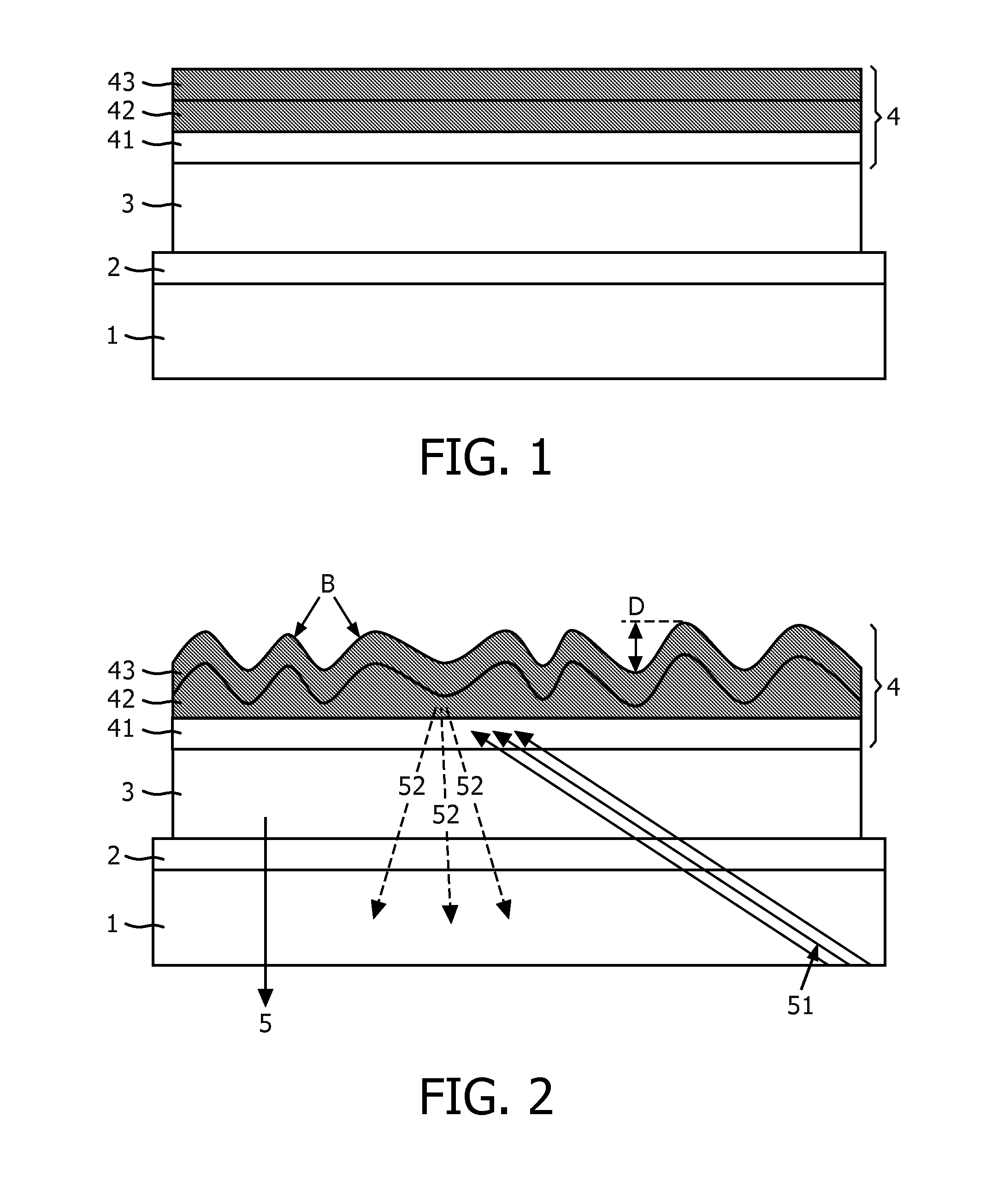
[0035]FIG. 2. shows the OLED device after applying the step of heating the electroluminescent layer 2, 3, 4 stack to a temperature, which is above the glass transition temperature Tg of the buckling layer 42 and be...


PUM


Abstract

The invention provides an OLED device with improved light out-coupling, which can be manufactured easy and reliable at low costs, which comprises an electroluminescent layer stack (2, 3, 4) on top of a substrate (1), where the electroluminescent layer stack (2, 3, 4) comprises an organic light-emitting layer stack (3) with one or more organic layers sandwiched between a first electrode (2) facing towards the substrate (1) and a 10 second electrode (4), where the second electrode (4) comprises a layer stack of at least a transparent conductive protection layer (41) on top of the organic light-emitting layer stack (3), a transparent organic conductive buckling layer (42) on top of the protection layer (41) having a glass transition temperature lower than the lowest glass transition temperature of the organic layers within the organic light-emitting layer stack (3) and a stress inducing layer 15 (43) on top of the buckling layer (42) to introduce stress to the buckling layer (42). The invention further relates to a method to manufacture such OLED devices with heating the electroluminescent layer (2, 3, 4) stack to a temperature, which is above the glass transition temperature of the buckling layer (42) and below the lowest glass transition temperature of the organic layers within the organic light-emitting layer stack (3) for a time period sufficient 20 to obtain buckles (B) within the buckling layer (42).

Description

FIELD OF THE INVENTION[0001]The invention relates to the field of organic electroluminescent devices with enhanced light out-coupling.BACKGROUND OF THE INVENTION[0002]Organic electroluminescent devices (or diodes) are devices, where organic molecules emit light when a driving voltage is applied to such organic electroluminescent devices (OLEDs). The OLEDs typically comprise a transparent substrate with an electroluminescent layer stack deposited on top of the substrate comprising an organic light emitting layer stack between two electrode layers, typically a transparent anode on top of the substrate and a reflective cathode on top of the organic layer stack. Since the organic molecules are sensitive to moisture and oxygen, the layer stack is encapsulated by a gastight cover lid sealed on top of the substrate. In order to operate the OLED, driving voltages in the order of a few volts, e.g. 2-15 V are applied.[0003]OLED devices are large area light sources intended for room illuminati...

Claims


Application Information

Patent Timeline
IPC IPC(8): H05B33/12H05B33/10
CPCH05B33/12H05B33/10H10K50/826H10K50/856H10K50/13H10K50/805H10K2102/351
Inventor BOERNER, HERBERT FRIEDRICHHUMMEL, HELGAGOLDMANN, CLAUDIA MICHAELA
Owner OLEDWORKS GMBH
Why Eureka
Try Eureka