High frequency power amplifier

a power amplifier and high frequency technology, applied in the direction of amplifiers, amplifiers with semiconductor devices only, amplifiers with semiconductor devices, etc., can solve the problems of low design freedom in adjusting the gain fluctuation, delay in thermal response of the amplifier, and degradation of evm (error vector magnitude) in the ofdm, etc., to suppress the degradation of evm

Active Publication Date: 2013-11-07
PANASONIC SEMICON SOLUTIONS CO LTD
View PDF0 Cites 13 Cited by
  • Summary
  • Abstract
  • Description
  • Claims
  • Application Information

AI Technical Summary

Benefits of technology

[0020]According to the above configuration, the third resistor, the fifth transistor, and the sixth transistor are the temperature compensation circuit that stabilizes the bias against the temperature change.
[0021]According to the present invention, the time until the temperature fluctuation due

Problems solved by technology

On the other hand, in order to increase the maximum output of the high frequency power amplifier, it is necessary to increase the number of transistors, or it is necessary to enlarge a size, which results in a delay of a thermal response of the amplifier.
During the increase of the temperature, a gain or a phase of the amplifier changes to fatally cause degradation of EVM (Error Vector Magnitude) in the OFDM.
This becomes a large issue whe

Method used


Image

  • High frequency power amplifier
  • High frequency power amplifier
  • High frequency power amplifier

Examples


first exemplary embodiment

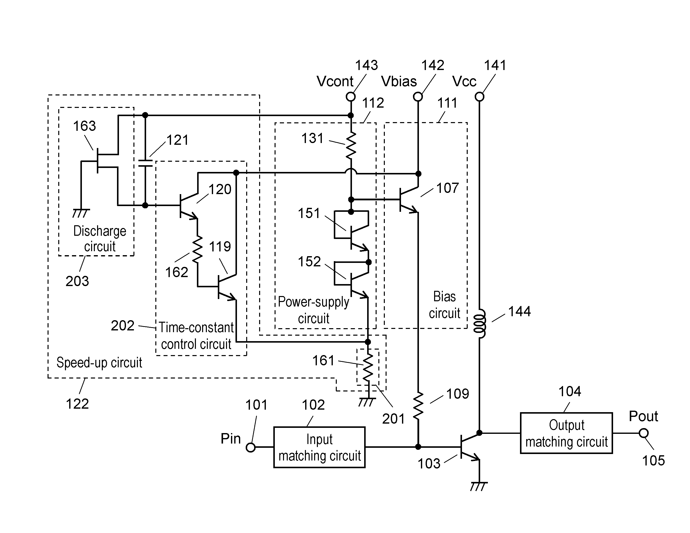
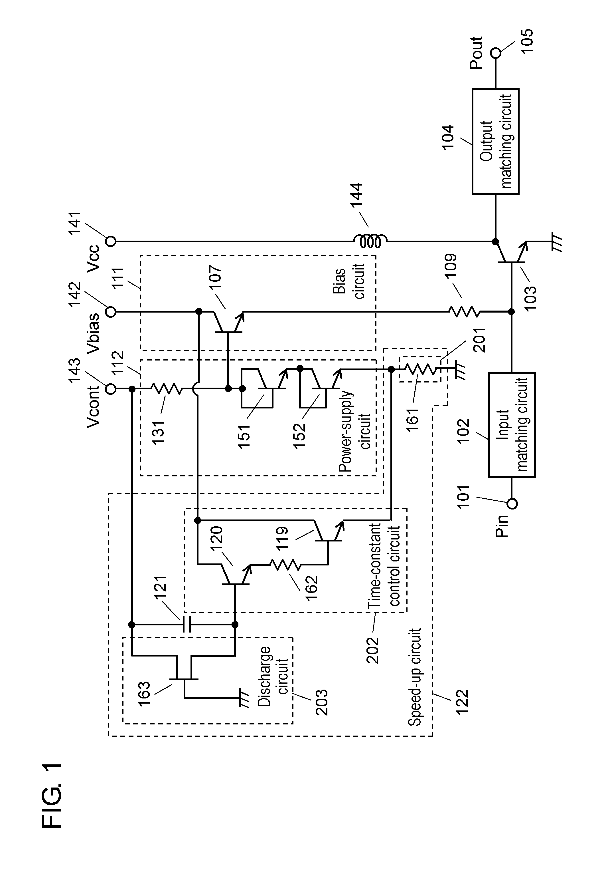
[0031]FIG. 1 is a circuit diagram of a high frequency power amplifier according to a first embodiment of the present invention. In the high frequency power amplifier of the first embodiment, mainly, provision of overshoot control circuit 201 facilitates determination or setting of an increasing amount when reference voltage Vref used to output a bias is transiently increased immediately after a rise of a control voltage of control voltage terminal 143.

[0032]The high frequency power amplifier in FIG. 1 includes input terminal 101, output terminal 105, input matching circuit 102, output matching circuit 104, amplification transistor 103, stabilizing resistor 109, bias circuit 111, power-supply circuit 112, speed-up circuit 122, collector power supply terminal 141, bias power supply terminal 142, control voltage terminal 143, and choke coil 144.

[0033]Amplification transistor 103 that is the first transistor performs power amplification of a high frequency signal.

[0034]Bias circuit 111 ...

second exemplary embodiment

[0047]FIG. 4 illustrates a circuit diagram of a high frequency power amplifier according to a second embodiment. The high frequency power amplifier of the second embodiment has the same configuration as the high frequency power amplifier of the first embodiment except the power-supply circuit, the same component is designated by the same numeral, and a different point is mainly described while the overlapping description is omitted.

[0048]Power-supply circuit 171 includes transistor 172 that is the fifth transistor, resistor 175 that is the fourth resistor, and transistor 173 that is the sixth transistor.

[0049]The collector of transistor 172 is connected to the base of bias transistor 107, and the emitter is grounded through resistor 161.

[0050]One end of resistor 175 is connected to the base of transistor 172, and the other end is grounded.

[0051]The collector of transistor 173 is connected to the collector of bias transistor 107, the base is connected to the base of bias transistor 1...

third exemplary embodiment

[0056]FIG. 5 illustrates a circuit diagram of a high frequency power amplifier according to a third embodiment. The high frequency power amplifier of the third embodiment has the same configuration as the high frequency power amplifier of the first embodiment except the power-supply circuit and the bias circuit, the same component is designated by the same numeral, and a different point is mainly described while the overlapping description is omitted.

[0057]Bias circuit 181 includes bias FET 182 that is the first FET supplying the bias to amplification transistor 103. The source of bias FET 182 is connected to the base of amplification transistor 103, and the gate of bias FET 182 is grounded through resistor 161.

[0058]Time-constant control circuit 202 includes transistor 119 that is the third transistor, resistor 162 that is the second resistor, and transistor 120 that is the fourth transistor. The emitter of transistor 119 is grounded through resistor 161. One end of resistor 162 is...


PUM


Abstract

Provided is a compact high frequency power amplifier having a high degree of freedom of design with respect to a gain fluctuation immediately after start-up of an amplifier. The high frequency power amplifier includes a speed-up circuit that transiently increases a reference voltage during rise of a control voltage to increase an amount of bias supplied to an amplification transistor from a bias circuit. The speed-up circuit includes a capacitor and an overshoot control circuit. The overshoot control circuit determines an increasing amount of the reference voltage when the reference voltage is transiently increased according to a charge amount charged in the capacitor, and the overshoot control circuit also determines a time constant in charging and discharging the capacitor.

Description

BACKGROUND[0001]1. Technical Field[0002]The present invention relates to a high frequency power amplifier, more specifically to a high frequency power amplifier used in mobile communication devices including a mobile phone.[0003]2. Background Art[0004]Nowadays, mobile communication devices such as a mobile phone not only make a telephone call but also become communication means for transmitting and receiving various pieces of data such as a mail and contents. Therefore, the mobile phone is equipped with a wireless LAN (Local Area Network) or the like.[0005]In the wireless LAN, an OFDM (Orthogonal Frequency Division Multiplexing) is used as a modulation wave in conducting high-speed data communication. Because high modulation accuracy is required in a system in which the OFDM is used, high linearity is demanded in the high frequency power amplifier. In order to meet the demand, the high frequency power amplifier is designed such that the sufficient linearity is obtained in the use ou...

Claims


Application Information

Patent Timeline
IPC IPC(8): H03F1/30
CPCH03F1/30H03F1/0261H03F3/245H03F2200/18H03F2200/555H03F1/302H03F3/191H03F1/565H03F2200/222H03F2200/387
Inventor WAKITA, KAZUYAKOIZUMI, HARUHIKOENOMOTO, SHINGOKAWANO, HIROAKI
Owner PANASONIC SEMICON SOLUTIONS CO LTD
Why Eureka
Try Eureka