Method and Cleaning Device for Cleaning and Checking a Particle Filter

Inactive Publication Date: 2013-11-14
DAIMLER AG
View PDF1 Cites 11 Cited by
  • Summary
  • Abstract
  • Description
  • Claims
  • Application Information

AI Technical Summary

Benefits of technology

[0013]Finally, it has been shown to be advantageous if an underpressure is supplied to the particle filter during the blowing out of the ash. This suction of the ash can take place from the end face that lies

Problems solved by technology

The process thereby requires

Method used


Image

  • Method and Cleaning Device for Cleaning and Checking a Particle Filter
  • Method and Cleaning Device for Cleaning and Checking a Particle Filter

Examples


Embodiment Construction

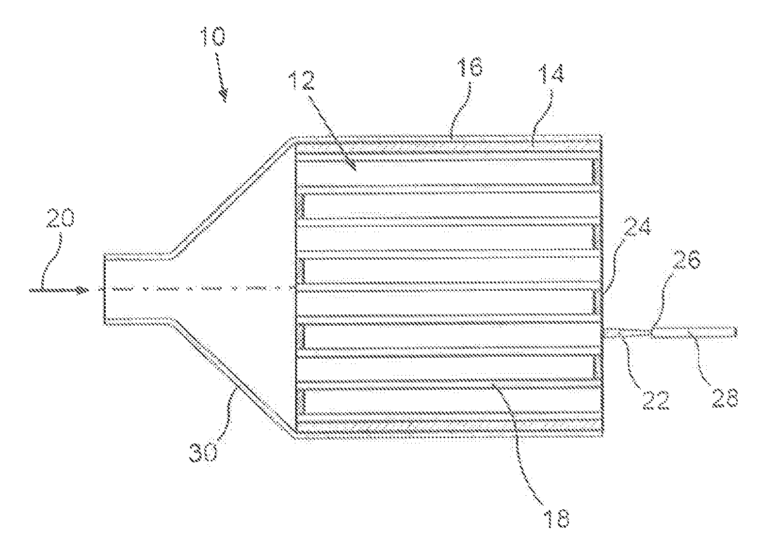
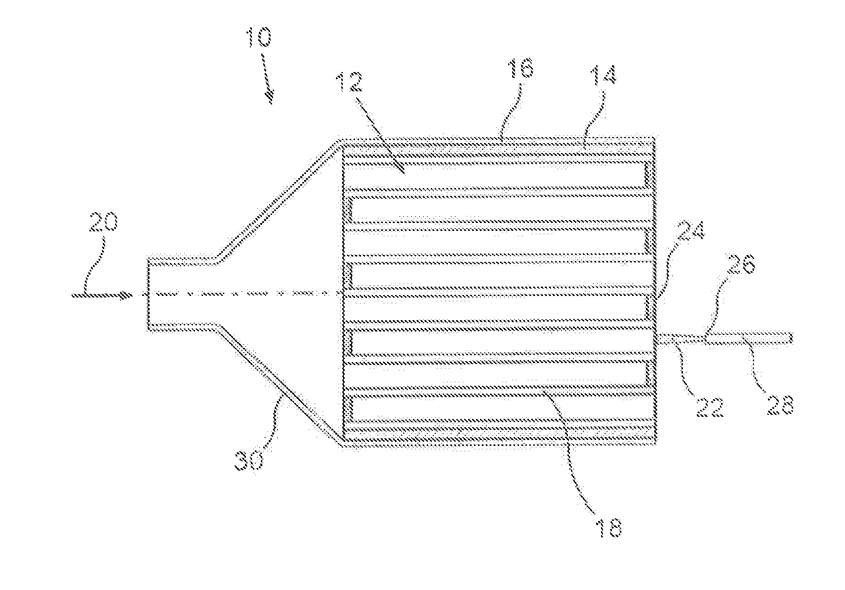
[0019]A particle filter 10 shown in the drawing serves for the removal of particles from the exhaust gas of an internal combustion engine of a motor vehicle operated with diesel, whereby it can be in particular a utility vehicle. With increasing duration of operation of the particle filter 10 more and more soot particles and ash are deposited on a substrate or filter material 12 of the particle filter 10 and the exhaust gas counter pressure of an exhaust gas system provided with the particle filter 10 increases. A removal of filtered-out soot particles takes place preferably during an operation of the motor vehicle through continuous oxidation by means of nitrogen dioxide contained in the exhaust gas (passive regeneration) and / or through thermal soot burn-off carried out from time to time (active regeneration). If a certain quantity of ash is collected a cleaning process is implemented, which is described in greater detail below. In the present case the cleaning process is carried o...


PUM

PropertyMeasurementUnit
Fractionaaaaaaaaaa
Fractionaaaaaaaaaa
Pressureaaaaaaaaaa

Abstract

A method for cleaning and checking a particle filter of a motor vehicle is provided. In a first step soot particles which have collected in the particle filter are burnt oil. In a second step ash located in the particle filter is blown, out using compressed air. A cleaning device for a particle filter of a motor vehicle is also provided.

Description

BACKGROUND AND SUMMARY OF THE INVENTION[0001]The invention relates to a method for cleaning and checking a particle filter of a motor vehicle, wherein in a first step soot particles which have collected in the particle filter are burnt. The invention further relates to a cleaning device for a particle filter.[0002]German patent document DE 103 21 290 A1 describes a method for cleaning a particle filter of a motor vehicle, wherein soot particles that have collected in the particle filter are burnt in a soot burn-off process. In a flushing process after the soot burn-off process ash particles that have collected in the particle filter are removed from the particle filter by means of a flushing medium passed through the particle filter. During the soot burn-off process an oxygen concentration in a hot air flow, to which the particle filter is subjected, is set to less than 10%. When this concentration is exceeded the soot burn-off process is halted in order to avoid uncontrollable soot...

Claims


Application Information

Patent Timeline
IPC IPC(8): B01D46/42
CPCF01N3/0232F01N3/0233F01N3/0237F01N11/002F01N2550/04Y02T10/40
Inventor ALBRECHT, ANDREASBENZ, PETEREMLEY, CHARLES W.GAERTNER, UWEMEDAU, CHRISTIAN
Owner DAIMLER AG
Why Eureka
Try Eureka