

Tangential cutting insert
a cutting edge and insert technology, applied in the direction of shaping cutters, turning machine accessories, manufacturing tools, etc., can solve the problems of shortened service life of inserts, deterioration of machining quality, high cutting resistance, etc., to enhance cutting power, reduce cutting resistance, and strengthen the strength of main cutting edges
- Summary
- Abstract
- Description
- Claims
- Application Information
AI Technical Summary
Benefits of technology
Problems solved by technology
Method used
Image

Examples
Embodiment Construction
[0020]Hereinafter, detailed embodiments according to the present disclosure are described. However, the present invention can be realized in other various forms, and is not limited to the embodiments explained herein. The figures attached to the present disclosure are merely for convenience of explanation, and the shapes and the relative scales may be exaggerated or distorted. Some portions of the figures which are not necessary for explaining the features of the present invention may be abridged for clearer explanation of the invention.
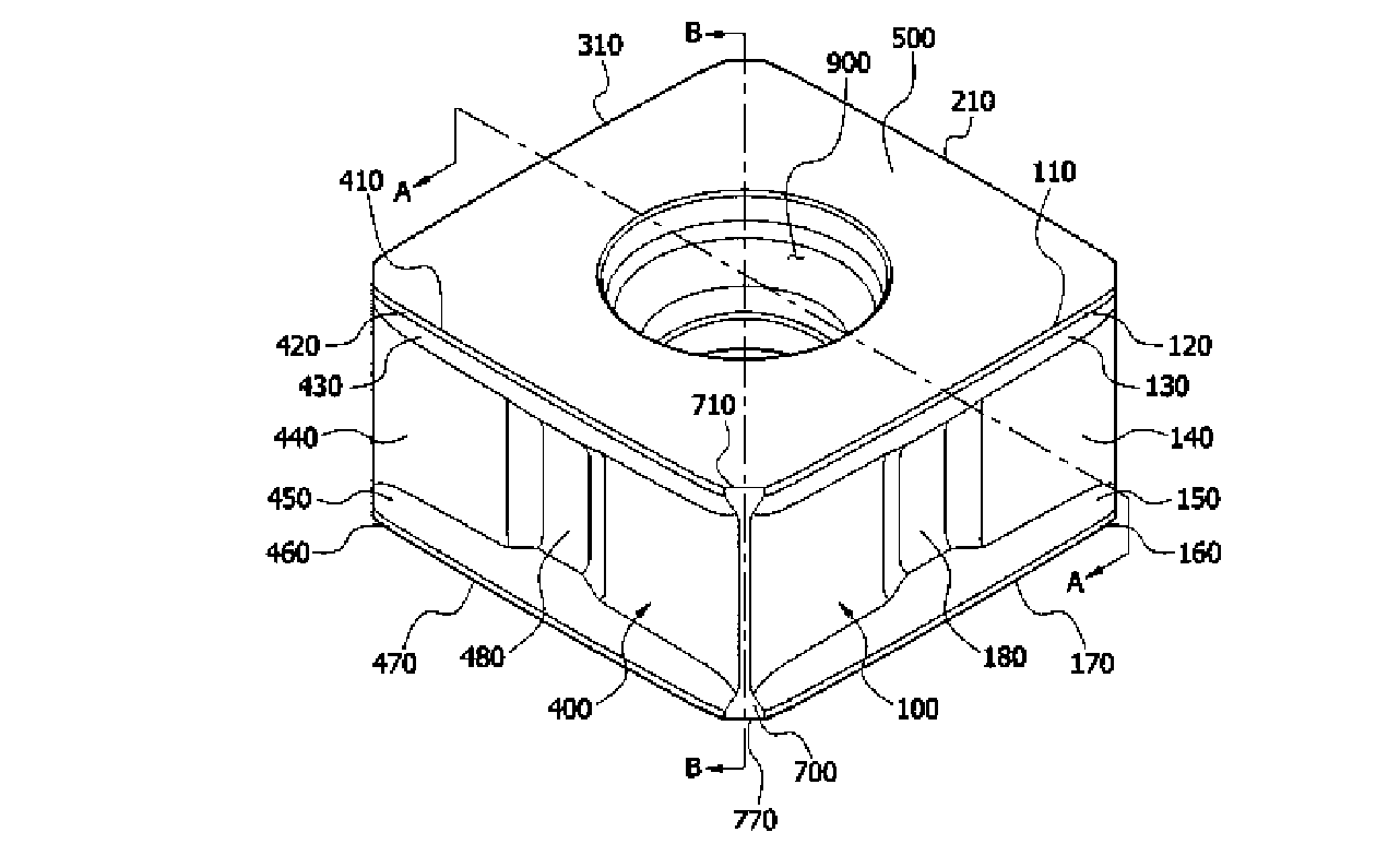
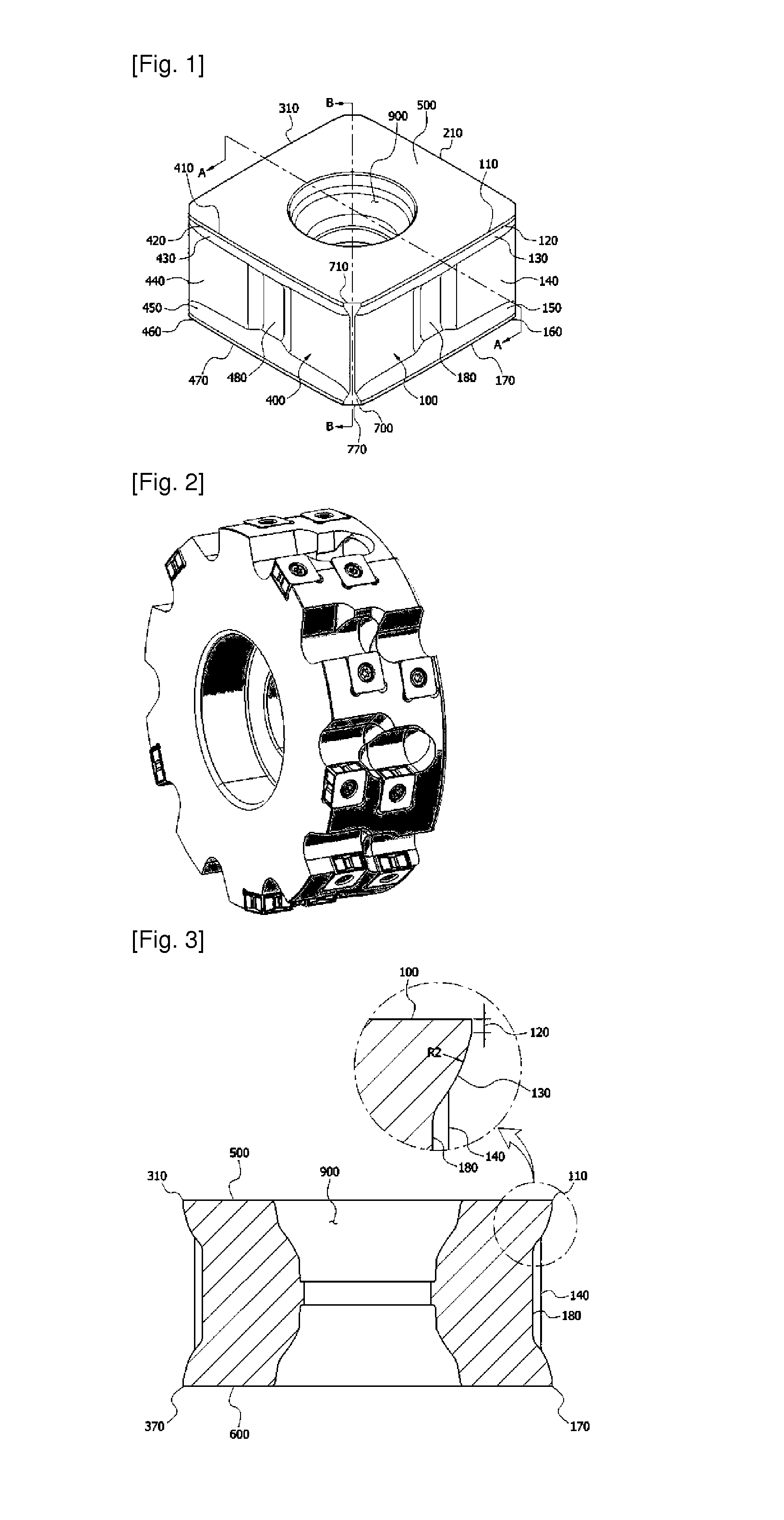
[0021]FIG. 1 is a perspective view of an insert in accordance with the present disclosure. These inserts are called tangential inserts, since they are mounted in a tangential orientation on a milling cutter by screws as shown in FIG. 2.
[0022]An insert of the present disclosure is hexahedral with a top face 500, a bottom face 600, and two pairs of opposing side faces 100,200,300,400. Main cutting edges 110,170,410,470 are formed on the borders of the ...
PUM
| Property | Measurement | Unit |
|---|---|---|
| radius of curvature | aaaaa | aaaaa |
| cutting resistance | aaaaa | aaaaa |
| strength | aaaaa | aaaaa |
Abstract
Description
Claims
Application Information