Space frame structure

a space frame and structure technology, applied in the field of space frame structure, can solve the problems of low structural efficiency, large number of components, and inability to optimise aerofoil structures, and achieve the effects of improving structural efficiency, reducing emissions, and increasing fuel efficiency

Inactive Publication Date: 2013-11-14
AIRBUS OPERATIONS LTD
View PDF21 Cites 14 Cited by
  • Summary
  • Abstract
  • Description
  • Claims
  • Application Information

AI Technical Summary

Benefits of technology

[0030]The space frame may replace the stringers traditionally used in an aerofoil torsion box structure. By providing the space frame with structural members extending between the opposing sides of the space frame, it also becomes possible to replace the ribs traditionally used in the torsion box.
[0031]The integrated strut sections of the space frame may provide a more structurally efficient design than individual ribs and stringers used in a conventional torsion box. The aerofoil structure may, therefore, be lighter, resulting in increased fuel efficiency and lower emissions, and reduced parts count resulting in reduced manufacturing and operating costs.
[0032]The structural members used to react out of plane loads between the covers may have a smaller volume than the ribs which they replace. The free internal volume within the wing may therefore be increased, resulting in an increase in the maximum volume of fuel which can be carried within the wing, thereby increasing the range of the aircraft.
[0033]The strut sections may be substantially aligned with the load carrying direction of the structure. By arranging the strut sections in the desired load carrying directions, the structure may be more structurally efficient that conventional longitudinal stringers and transverse ribs. The directional properties of a material such as carbon fibre may therefore be used to maximise the efficiency of the structure by aligning the predominant direction of the fibres in the ply layers within each strut section with the local load carrying direction.

Problems solved by technology

The direct replacement of metallic components with similar components formed using composite materials often fails to make the most efficient use of composite materials.
Known composite, or hybrid, aerofoil structures are therefore not optimised and have a large number of components.
The direct replacement of metallic components with similar composite components also fails to maximise the properties and manufacturing processes which are possible with composite materials.

Method used


Image

  • Space frame structure
  • Space frame structure
  • Space frame structure

Examples


Embodiment Construction

)

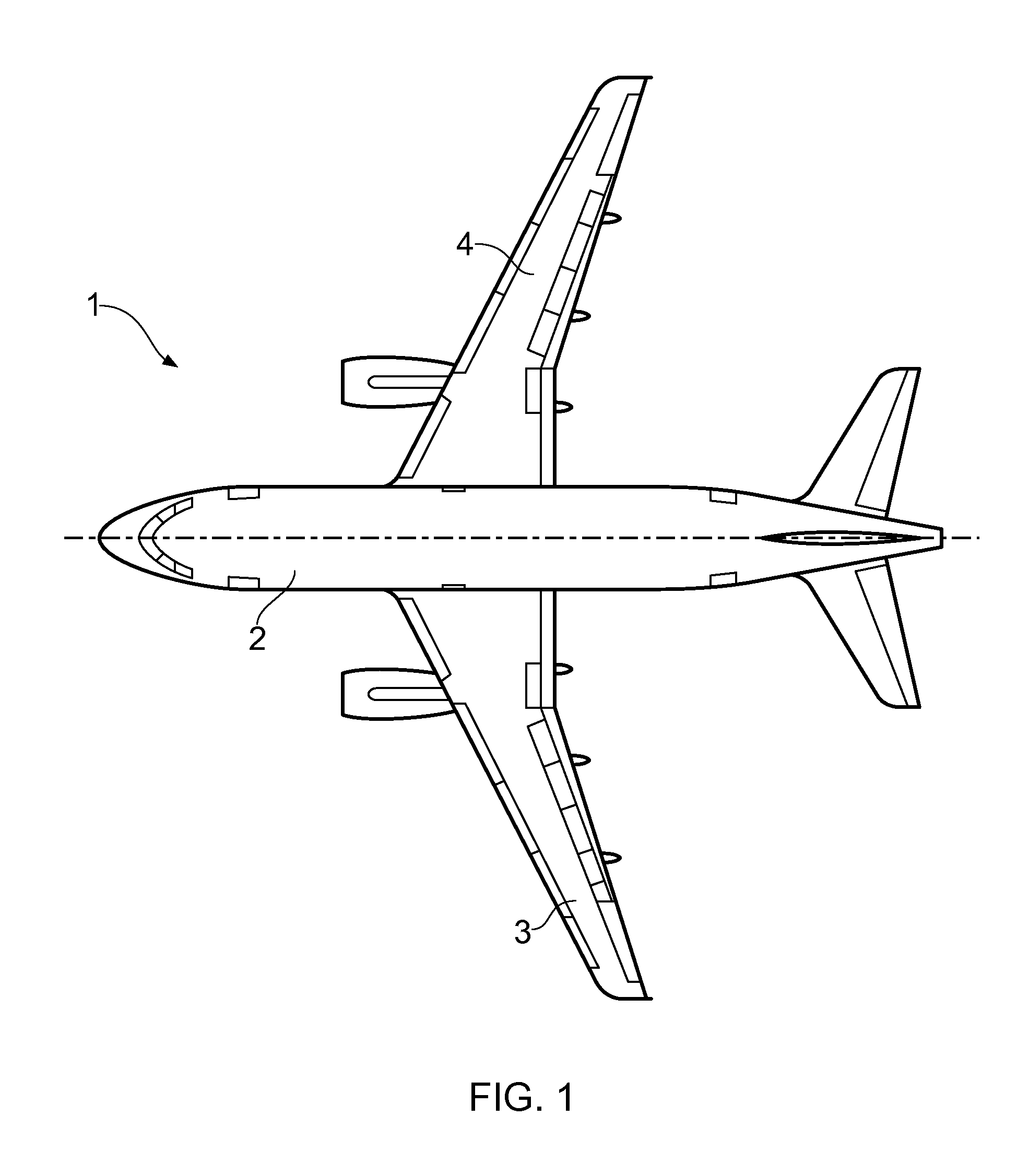
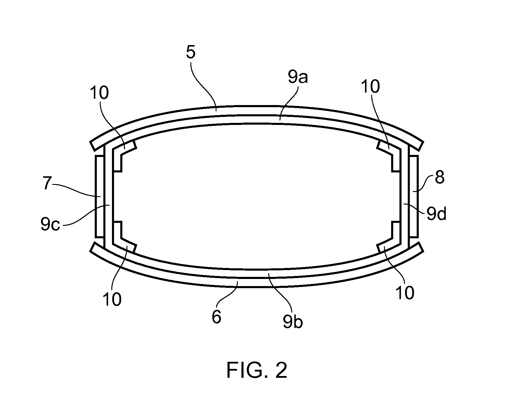
[0055]FIG. 1 illustrates an aircraft 1 having a fuselage 2 and wings 3, 4. As shown schematically in FIG. 2, the wing 3 has a torsion wing box structure comprising upper and lower covers 5, 6; front and rear spar webs 7, 8; a space frame lattice-type cage 9; and spar caps 10. The covers 5, 6 define, in part, the upper and lower aerodynamic surfaces of the aerofoil profile of the wing 3. The spars webs 7, 8 and their respective spar caps 10 together form the front and rear spars of the wing, which extend spanwise in the wing longitudinal direction. The wing 3 also comprises leading and trailing edge structures (not shown) that complete the aerofoil profile, and various other components which have been omitted from FIG. 2 so as not to detract from the understanding of the invention.

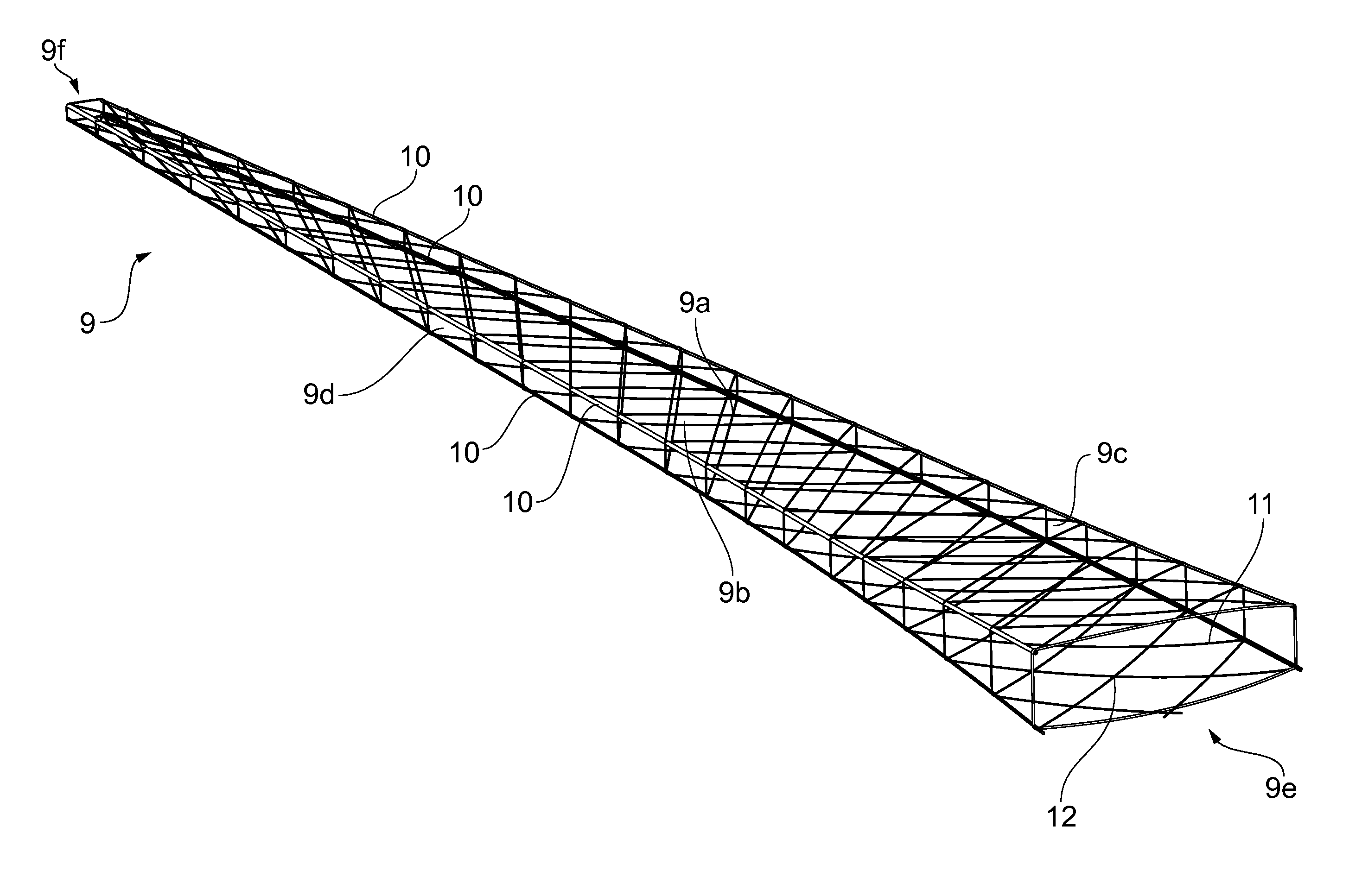
[0056]The space frame cage 9, shown in FIG. 3, is an integrally formed space frame structure formed from laminate composite materials, e.g. carbon fibre reinforced polymer plies. The cage 9 has upper and l...


PUM

PropertyMeasurementUnit
structureaaaaaaaaaa
perimeteraaaaaaaaaa
space frame structureaaaaaaaaaa

Abstract

A structure comprising a space frame including a plurality of strut sections which cross at one or more locations within the space frame to define a node at each respective crossing location, wherein the strut sections are laminates comprising a plurality of ply layers, and wherein the ply layers of the crossing strut sections are interleaved at the node(s). Also a method of forming the structure. Also An aerofoil structure, comprising a space frame defining a cage adapted to receive upper and lower covers so as to form upper and lower aerodynamic surfaces of the aerofoil, and at least one spar extending generally spanwise across the structure, wherein the spar includes a spar web and upper and lower spar caps, and wherein the spar web is disposed on one of an interior or exterior side of the cage, and the spar caps are attached to the other of the interior or exterior side of the cage.

Description

FIELD OF THE INVENTION[0001]The invention relates to a structure comprising a space frame, and a method of forming a space frame structure.BACKGROUND OF THE INVENTION[0002]A typical aerofoil structure, e.g. for aircraft, comprises a torsion “wing box” having front and rear longitudinal spars, a plurality of transverse ribs attached to the front and rear spars and upper and lower covers extending between the front and rear spars. A plurality of longitudinal stringers are typically attached to or integrally formed with the covers to stiffen and strengthen the covers so that the thickness, and therefore weight, of the covers can be reduced. The ribs, spars and covers, and sometimes also the stringers, are each manufactured as separate components which are fastened or otherwise fixed together to form the aerofoil structure.[0003]Over recent decades there has been a move towards greater use of composite materials in aerofoil structures to replace traditional metallic materials with the a...

Claims


Application Information

Patent Timeline
Patent Type & Authority Applications(United States)
IPC IPC(8): E04B1/19F01D5/14
CPCE04B1/19F01D5/147B64C3/22B29L2031/3076B29C70/38B29D99/0007Y10T156/10Y02T50/40
Inventor WILLIAMS, STEPHEN
Owner AIRBUS OPERATIONS LTD
Why Eureka
Try Eureka