Method of forming polymeric foam and related foam articles

a polymeric foam and foam article technology, applied in the field of polymeric foam, can solve the problems of difficult to maintain a quality, difficult to process certain polymeric materials (e.g., low melt strength polymeric materials) as foams, and cells to grow and/or become distorted, etc., to achieve softening of pellets, control viscosity, and facilitate melting

Active Publication Date: 2013-11-14
MUCELL EXTRUSION
View PDF27 Cites 56 Cited by
  • Summary
  • Abstract
  • Description
  • Claims
  • Application Information

AI Technical Summary

Benefits of technology

[0029]As noted above, some embodiments utilize one or more skin layer(s) which are co-extruded with the polymer foam layer. Without being bound by any theory, it is believed that the skin layer(s) can lead to a number of advantageous effects including: providing a support structure against which the foam layer may expand; encapsulating the foam layer (e.g., when an upper and lower skin layer is provided) to increase the rate of cooling; and, when co-extruded, increasing the pressure in the die which can lead to greater pressure drops when exiting the die which, in turn, can enhance the cell nucleation process. These effects can limit cell growth and / or coalescence thereby contributing to forming a high quality foam cell structure.
[0030]In embodiments which include skin layer(s), the layer(s) may be formed of polymeric material that is different than the polymeric material used to form the foam layer. In some embodiments, the skin layer material is immiscible with the polymeric foam material. The skin layer material should also be compatible with its purpose. For example, the skin layer material should be one that readily separates from the polymer foam material during a peeling operation if that is desired. In some cases, the skin layer material may be a relatively inexpensive polymer. Suitable skin layer materials may include polyolefins such as polyethylene (e.g., low-density polyethylene) and polypropylene. In embodiments in which the skin layer(s) are retained as a portion of the final article, the skin layer material may be selected to impart desired characteristics to the article (e.g., stiffness).
[0031]In a typical process, the polymeric material may be introduced into the extruder using a standard hopper 30. The screw is connected, at its upstream end, to a drive motor 32 which rotates the screw within the barrel. Positioned along the barrel are temperature control units 34. The control units can be electrical heaters, can include passageways for temperature control fluid, and or the like. Units can be used to heat a stream of polymeric material within the barrel to facilitate melting, and / or to cool the stream to control viscosity. The temperature control units can operate differently at different locations along the barrel, that is, to heat at one or more locations, and to cool at one or more different locations. Any number of temperature control units can be provided. Temperature control units also can be supplied to heat the die to which the extrusion system is connected.
[0032]The polymeric material may be provided in pellet form and introduced into the polymeric processing space from the hopper. The polymeric material is conveyed in a downstream direction as the screw rotates. Heat and shear forces arising from the rotating screw, act to soften the pellets. Eventually, the softened pellets have been gelated, that is, welded together to form a uniform fluid stream substantially free of air pockets.
[0033]As noted above, the methods may involve using a blowing agent. In some embodiments and as shown in FIG. 1, a physical blowing agent may be introduced into the stream of polymeric material through the blowing agent port. In other embodiments, a chemical blowing agent may be used. The chemical blowing agent may be used along with, or instead, of a physical blowing agent. The chemical blowing agents may be blended with, or added to, the polymeric material pellets or otherwise introduced into the stream. A blowing agent port may not be utilized when using a chemical blowing agent. Any of a wide variety of known chemical blowing agents may be used.
[0034]In embodiments in which a physical blowing agent is used, the physical blowing agent can be introduced from a blowing agent source 36 connected to the blowing agent port. Any of a wide variety of physical blowing agents known to those of ordinary skill in the art such as hydrocarbons, chlorofluorocarbons, nitrogen, carbon dioxide, and the like, and mixtures, can be used. In some preferred embodiments, the source provides carbon dioxide, or nitrogen, or a mixture thereof as a blowing agent. Blowing agents that are in the supercritical state in the extruder may be preferred in some embodiments, particularly supercritical carbon dioxide and / or nitrogen.

Problems solved by technology

It can be challenging to process certain polymeric materials (e.g., low melt strength polymeric materials) as foams.
For example, it can be challenging to maintain a quality (e.g., fine) cell structure and / or good surface appearance when processing certain polymeric materials because there is a tendency for the foam cells to grow and / or become distorted.
The large and / or distorted cells can also compromise the properties (e.g., strength) of the resulting foams.

Method used


Image

  • Method of forming polymeric foam and related foam articles
  • Method of forming polymeric foam and related foam articles
  • Method of forming polymeric foam and related foam articles

Examples


example 1

PEBAX®

[0063]This example illustrates the production of a 3-layer polymer film comprising a PEBAX® foam layer and two solid LDPE skin layers which were subsequently separated from the PEBAX® foam layer.

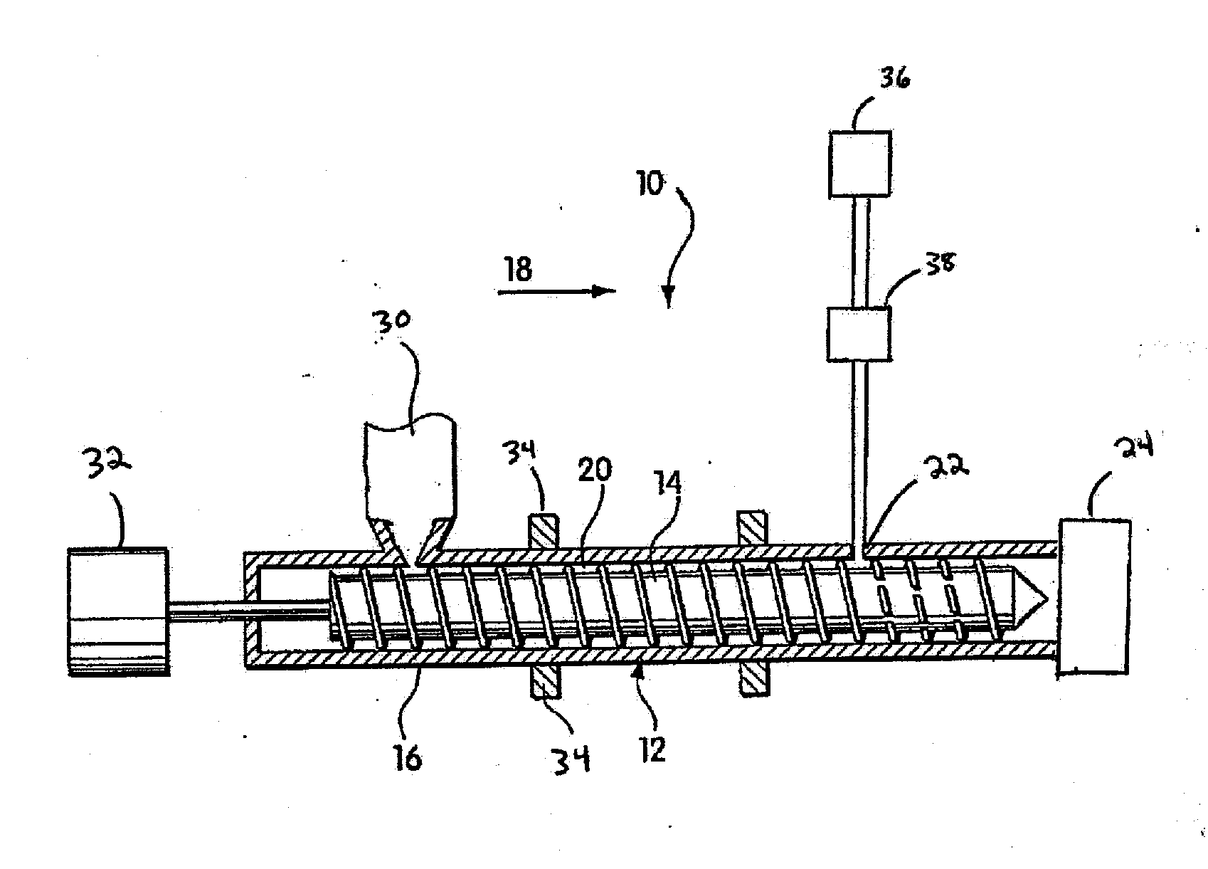
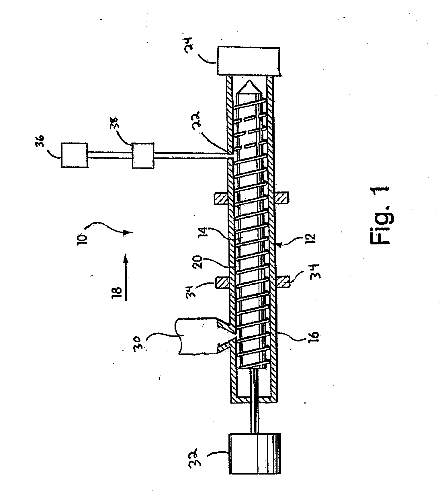
[0064]A stream of polyether-block-amide was created in an extruder, as described above. Nitrogen was introduced through a multi-hole blowing agent port into the stream and created a mixture of nitrogen and PEBAX®. The percentage of N2 by weight is approximately 0.1% of the total mixture. The stream is mixed together in the extruder to form a single-phase solution.

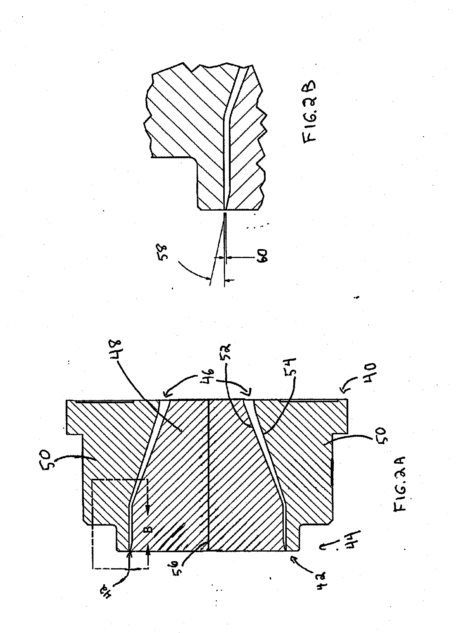
[0065]Meanwhile, streams of LDPE (un-foamed) were introduced into the co-extrusion die (as the outside layers). With all 3 streams in the die head, they reached the exit and the pressure fell at the lip exit. The pressure reduction caused the middle layer to foam. The die lip taper angle was between 4 and 20 degrees while the gap was less than 0.012″.

[0066]The PEBAX® foam became encapsulated between the two skin layers as air ...

example 2

PVDF

[0068]This example illustrates the production of a 3-layer film comprising a polyvinylidene fluoride (PVDF) foam layer and two solid LDPE skin layers which were subsequently separated from the PVDF foam layer.

[0069]A stream of PVDF was created in an extruder. Nitrogen was introduced through a multi-hole blowing agent port into the stream and creates a mixture of nitrogen and PVDF. The percentage of N2 by weight is approximately 0.1% of the total mixture. The stream was mixed together to form a single-phase solution.

[0070]Meanwhile, 2 streams of LDPE (un-foamed) were introduced into the co-extrusion die (as the outside layers). With all 3 streams in the die head, they reached the exit and the pressure fell at the lip exit. The pressure reduction caused the middle layer to foam. The die lip taper angle was between 4 and 20 degrees while the gap was less than 0.012″.

[0071]The PVDF foam became encapsulated between two skin layers as air was used to blow up and make the internal bubb...

example 3

PLA

[0073]This example illustrates the production of a 3-layer film comprising a polylactide or poly(lactic acid) (PLA) foam layer and two solid LDPE skin layers which were subsequently separated from the PVDF foam layer.

[0074]A stream of PLA was created in an extruder. Nitrogen was introduced through a multi-hole blowing agent port into the stream and creates a mixture of nitrogen and PVDF. The percentage of N2 by weight is approximately 0.1% of the total mixture. The stream was mixed together to form a single-phase solution.

[0075]Meanwhile, 2 streams of LDPE (un-foamed) were introduced into the co-extrusion die (as the outside layers). With all 3 streams in the die head, they reached the exit and the pressure fell at the lip exit. The pressure reduction caused the middle layer to foam. The die lip taper angle was between 4 and 20 degrees while the gap was less than 0.012″.

[0076]The PLA foam became encapsulated between two skin layers as air was used to blow up and make the internal...


PUM

PropertyMeasurementUnit
angleaaaaaaaaaa
angleaaaaaaaaaa
taper angleaaaaaaaaaa

Abstract

Methods of forming polymeric foams are provided. The methods may involve co-extruding a foam layer along with one or more skin layers. In some embodiments, the skin layer(s) may be removed (e.g., in a peeling operation); while, in other embodiments, the skin layer(s) may form part of the final article. The methods are particularly well suited for producing polymeric foams from polymeric materials that are considered to be difficult to foam by those of skill in the art.

Description

RELATED APPLICATIONS[0001]This application claims priority to U.S. Provisional Patent Application Ser. No. 61 / 618,281, which was filed on Mar. 30, 2012 and is incorporated herein by reference in its entirety.FIELD OF INVENTION[0002]The invention relates generally to polymeric foam and more particularly to a method of forming polymeric foam and related foam articles.BACKGROUND OF INVENTION[0003]Polymeric foams include a plurality of cells (or voids) formed within a polymer matrix. By replacing solid plastic with voids, polymeric foams use less raw material than solid plastics for a given volume. Thus, raw material savings increase as the density of a foam decreases.[0004]It can be challenging to process certain polymeric materials (e.g., low melt strength polymeric materials) as foams. For example, it can be challenging to maintain a quality (e.g., fine) cell structure and / or good surface appearance when processing certain polymeric materials because there is a tendency for the foam ...

Claims


Application Information

Patent Timeline
Patent Type & Authority Applications(United States)
IPC IPC(8): B29C44/56B29C48/09B29C48/10B29C48/32
CPCB29C44/56B29C47/20B29K2995/0063B29K2995/0068B29L2007/00B29K2027/16B29K2075/00B29K2077/00B29C44/468B29C44/5654B29C47/0021B29C47/0026B29C47/0042B29C47/0066B29C47/065B29C47/1081B29C47/14B29K2267/046B29C48/297B29C48/08B29C48/10B29C48/0012B29C48/0022B29C48/21B29C48/305B29C48/32C08J9/122C08J2203/06C08J2201/03C08J9/34B29C48/09C08J2377/00C08J2387/00C08J2423/06C08J2327/16C08J2367/04
Inventor DIX, SAMUEL EDWARDANDERSON, JERE R.LINDENFELZER, MARK E.
Owner MUCELL EXTRUSION
Why Eureka
Try Eureka