Impeller for catheter pump

a technology of pump and catheter, which is applied in the field of pumps, can solve the problems of insufficient flow, high mortality rate, and inability to advance percutaneously,

Active Publication Date: 2013-11-14
TC1 LLC
View PDF1 Cites 75 Cited by
  • Summary
  • Abstract
  • Description
  • Claims
  • Application Information

AI Technical Summary

Benefits of technology

[0017]In another embodiment, a percutaneous heart pump system is disclosed. The system can comprise an impeller disposed at a distal portion of the system, the impeller sized and shaped to be inserted into a vascular system of a patient through a percutaneous access site having a size less than about 21 FR. The impeller can be configured to pump blood in the vascular system at a flow rate of at least about 3.5 liters per minute.
[0018]In another embodiment, a percutaneous heart pump system is disclosed. The system can include an impeller comprising one or more blades in a single row. The impeller can be disposed at a distal portion of the system. The impeller can be sized and shaped to be inserted through a vascular system of a patient. The impeller can be configured to pump blood through at least a portion of the vascular system at a flow rate of at least about 2.0 liters per minute when the impeller is rotated at a speed less than about 21,000 revolutions per minute.

Problems solved by technology

Heart disease is a major health problem that has high mortality rate.
Fixed cross-section ventricular assist devices designed to provide near full heart flow rate are either too large to be advanced percutaneously (e.g., through the femoral artery without a cutdown) or provide insufficient flow.
While the flow rate of a rotary pump can be increased by rotating the impeller faster, higher rotational speeds are known to increase the risk of hemolysis, which can lead to adverse outcomes and in some cases death.

Method used


Image

  • Impeller for catheter pump
  • Impeller for catheter pump
  • Impeller for catheter pump

Examples


Embodiment Construction

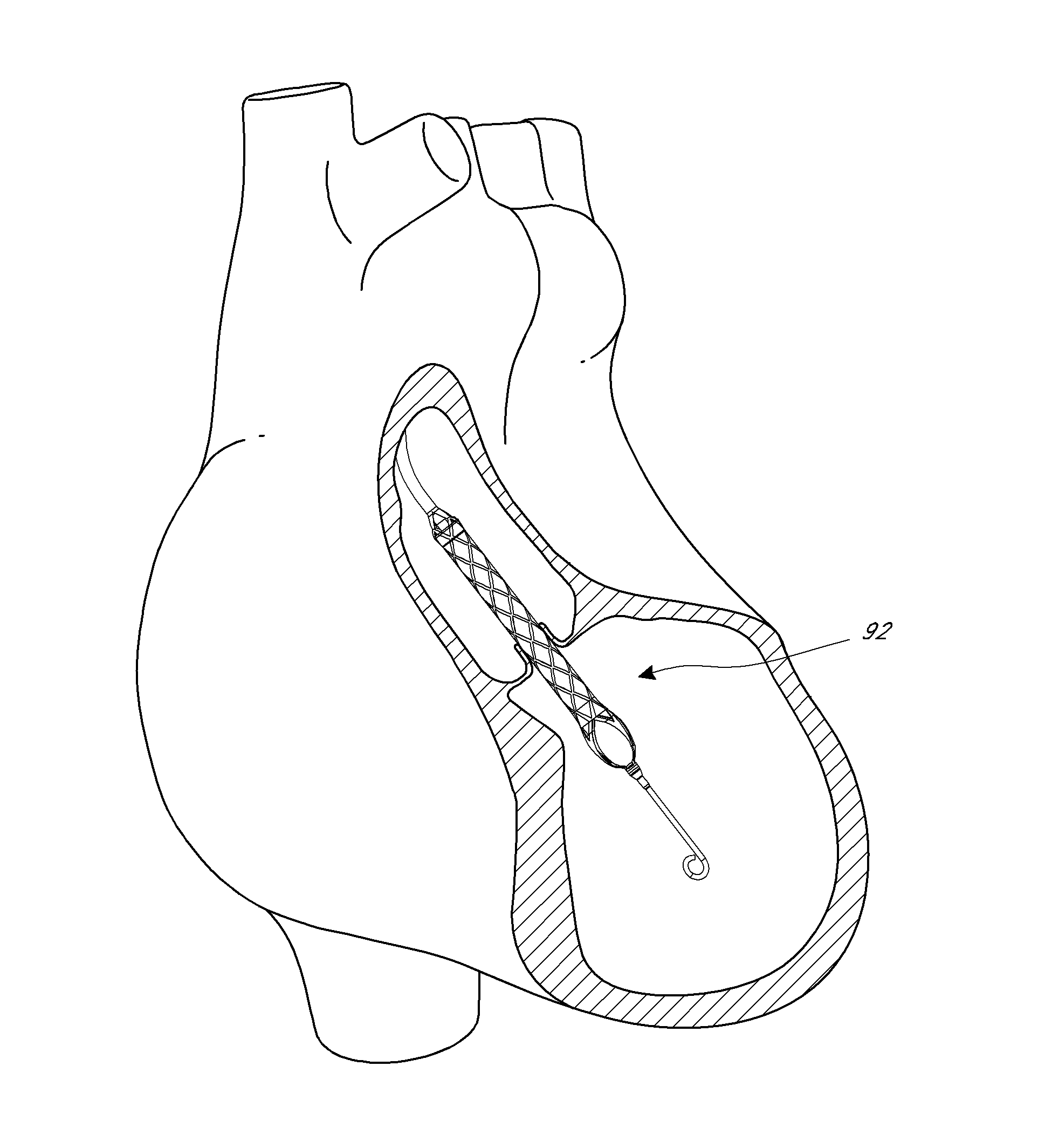
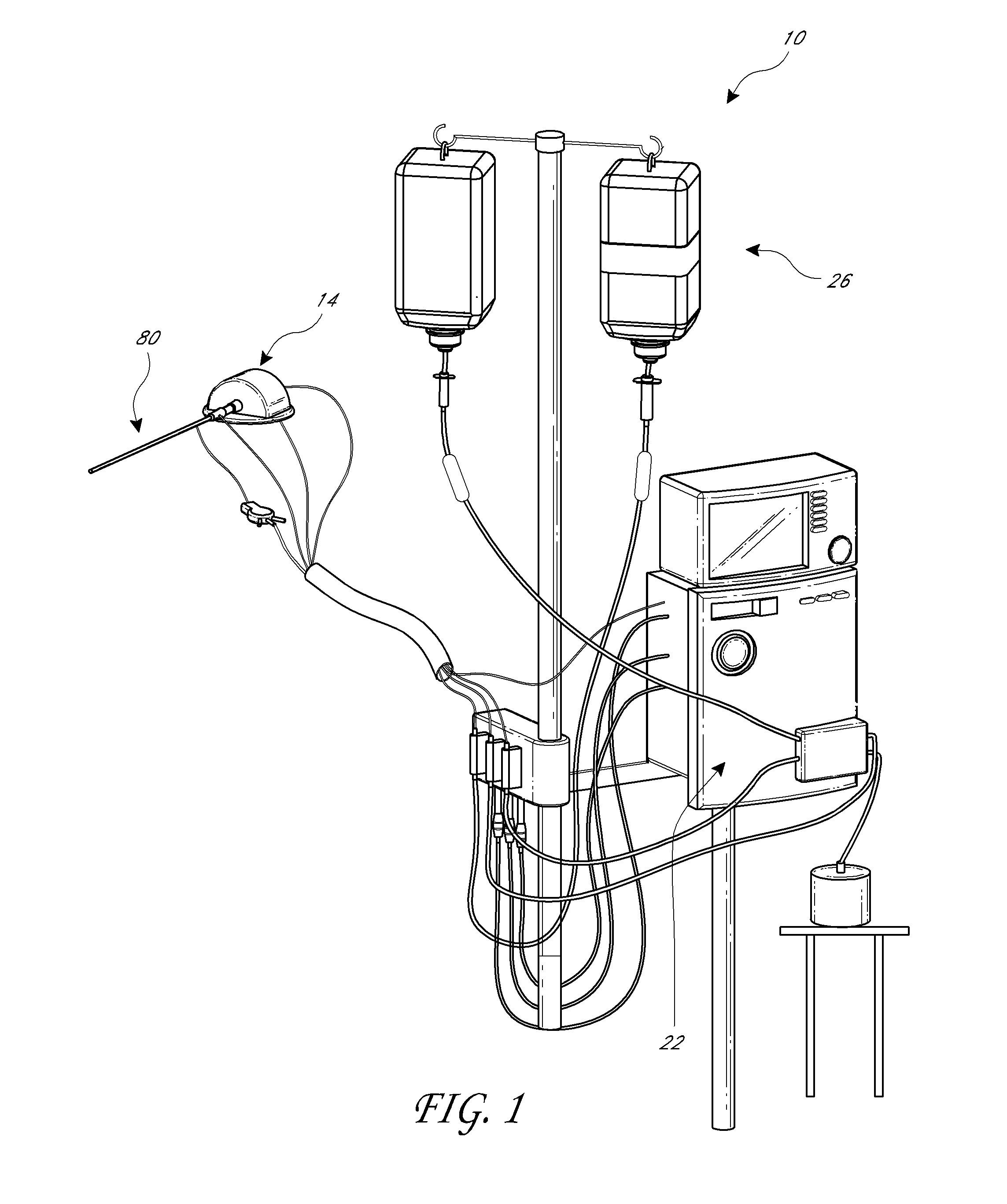
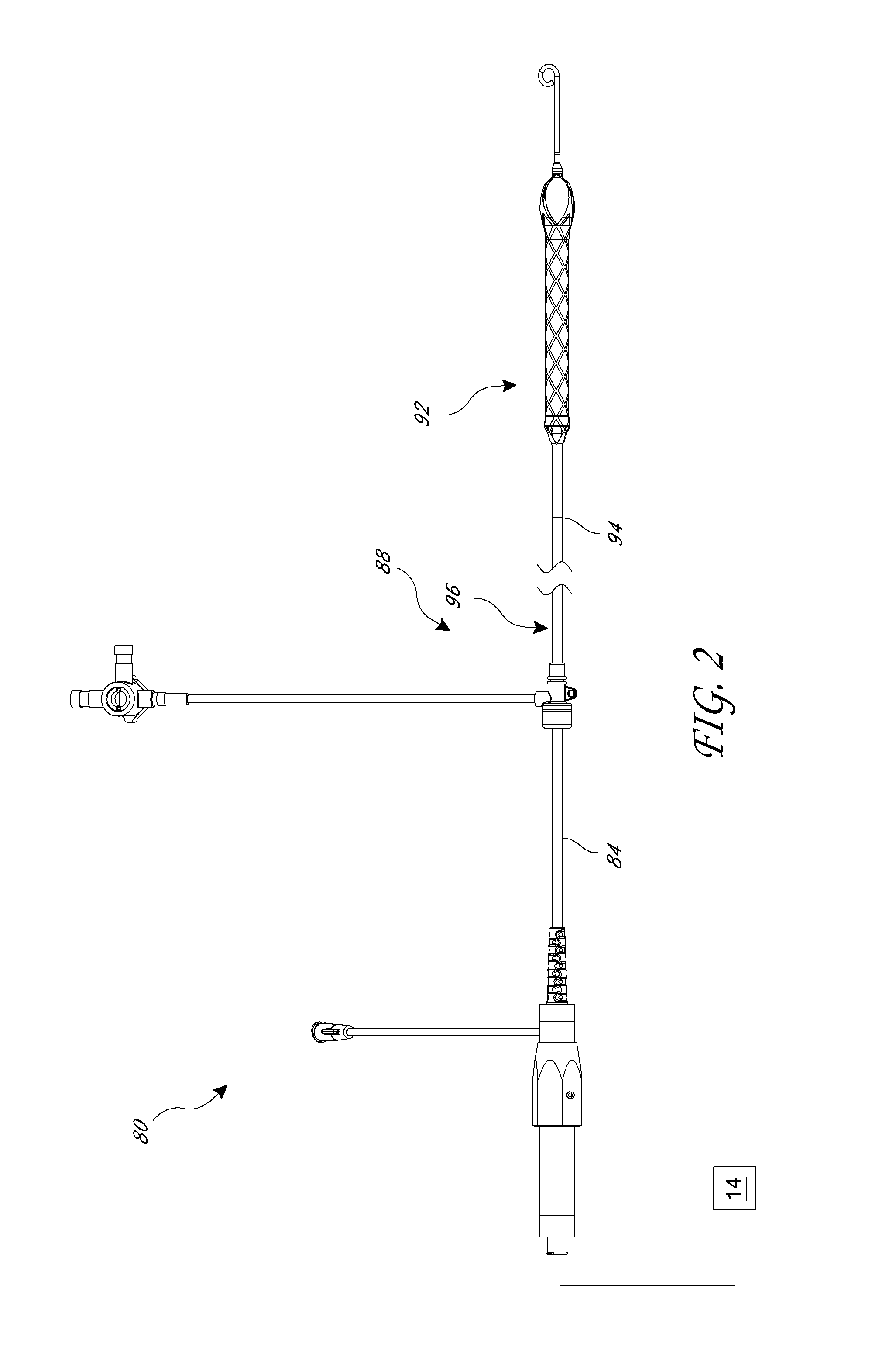
[0036]This application is directed to apparatuses for inducing motion of a fluid relative to the apparatus. In particular, the disclosed embodiments generally relate to various configurations for an impeller disposed at a distal portion of a percutaneous catheter pump. For example, FIGS. 1-4 show aspects of an exemplary catheter pump 10 that can provide high performance flow rates. The exemplary pump 10 includes a motor driven by a controller 22. The controller 22 directs the operation of the motor 14 and an infusion system 26 that supplies a flow of infusant or infusate in the pump 10. A catheter system 80 that can be coupled with the motor 14 houses an impeller within a distal portion thereof. In various embodiments, the impeller is rotated remotely by the motor 14 when the pump 10 is operating. For example, the motor 14 can be disposed outside the patient. In some embodiments, the motor 14 is separate from the controller 22, e.g., to be placed closer to the patient. In other embo...


PUM


Abstract

An impeller for a pump is disclosed herein. The impeller can include a hub having a fixed end and a free end. The impeller can also have a plurality of blades supported by the hub. Each blade can have a fixed end coupled to the hub and a free end. The impeller can have a stored configuration and a deployed configuration, the blades in the deployed configuration extending away from the hub, and the blades in the stored configuration being compressed against the hub.

Description

INCORPORATION BY REFERENCE TO ANY PRIORITY APPLICATIONS[0001]Any and all applications for which a foreign or domestic priority claim is identified in the Application Data Sheet as filed with the present application, including U.S. Application No. 61 / 646,827 and U.S. Application No. 61 / 667,875, are hereby incorporated by reference under 37 CFR 1.57.BACKGROUND OF THE INVENTION[0002]1. Field of the Invention[0003]This application is directed to pumps for mechanical circulatory support of a heart. In particular, this application is directed to various implementations of an impeller that can be used in a catheter pump.[0004]2. Description of the Related Art[0005]Heart disease is a major health problem that has high mortality rate. Physicians increasingly use mechanical circulatory support systems for treating heart failure. The treatment of acute heart failure requires a device that can provide support to the patient quickly. Physicians desire treatment options that can be deployed quick...

Claims


Application Information

Patent Timeline
Patent Type & Authority Applications(United States)
IPC IPC(8): A61M1/10A61M60/13A61M60/174A61M60/216A61M60/411A61M60/508A61M60/806A61M60/81A61M60/857
CPCA61M1/101F04C2270/0421A61M2205/3334A61M60/857A61M60/81A61M60/216A61M60/508A61M60/13A61M60/806A61M60/808A61M60/546A61M60/148A61M60/414A61M60/174A61M60/411F04D29/183
Inventor ZENG, ZIJINGYUEN, PHYLLISBUTLER, MICHAEL R.
Owner TC1 LLC
Why Eureka
Try Eureka