Method of vertically assembling a generator of a wind turbine

a technology of wind turbine and generator, which is applied in the direction of wind turbine generator, wind energy generation, dynamo-electric machines, etc., can solve the problems of lack of stiffness and resulting deformation, large deformation, and large size of wind turbine generators, and achieve the effect of increasing the stability

Active Publication Date: 2013-11-21
SIEMENS GAMESA RENEWABLE ENERGY AS
View PDF11 Cites 0 Cited by
  • Summary
  • Abstract
  • Description
  • Claims
  • Application Information

AI Technical Summary

Benefits of technology

[0027]The position of the stator relative to the rotor can therefore be exactly determined, so that the stator can be lowered into the rotor with the correct alignment. The rotor can be secured to the horizontal assembly support using any appropriate fastening means, for example vertical bolts or threaded rods that extend through the assembly support and into corresponding threaded bushings of the rotor. Such threaded rods can pass through corresponding openings in the assembly table and into bushings of the rotor. However, in a preferred embodiment of the invention, when spacer blocks are used, a spacer block preferably comprises one or more through-openings to...

Problems solved by technology

Wind turbine generators can be very large and accordingly very heavy.
A further challenge associated with large structures such as a cylindrical hollow rotor of several meters in diameter is the inherent lack of stiffness and resulting deformation.
The weight of the rotor itself can cause considerable deformation.
Such support rings require maintenance, servicing, and storage, and therefore add to the overall cost of construction.
Furthermore, such parts can fail and result in an accidental contact between rotor and stator during marriage.
A deformation of the rotor can result in a misalignment between connecting parts such as rotor, bearing and stator due to an erroneous offset at their interfaces.
A further problem lies in mounting bolts through matching holes in...

Method used


Image

  • Method of vertically assembling a generator of a wind turbine
  • Method of vertically assembling a generator of a wind turbine
  • Method of vertically assembling a generator of a wind turbine

Examples


Embodiment Construction

[0037]In the diagrams, like numbers refer to like objects throughout. Objects in the diagrams are not necessarily drawn to scale.

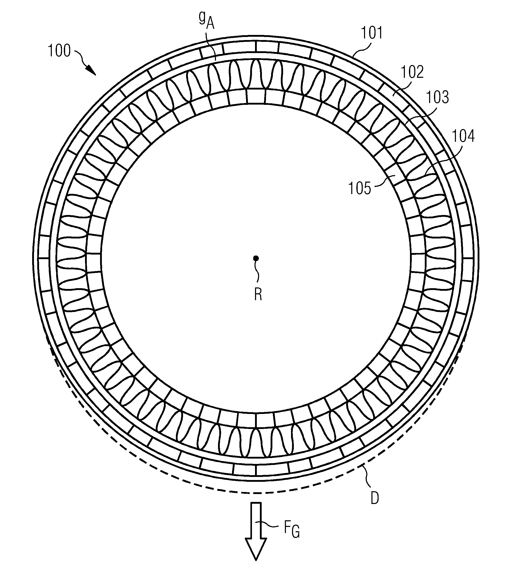
[0038]FIG. 1 shows components of a direct-drive permanent-magnet generator 100 during a prior art horizontal assembly process. Here, an outer rotor 101 is being supported by some holding means or support structure (not shown in the diagram) such that its rotational axis R is essentially horizontal, i.e. parallel to ground level. Usually, the rotor 101 and main bearing are mounted to an upright support, so that the main body of the rotor 101 protrudes horizontally from the upright support. The rotor 101 is realised to hold many permanent magnets 102 on its interior surface. A stator 103, with windings 104 mounted on a main shaft 105, must be inserted into the rotor 101. During this “horizontal marriage” it is of paramount importance that the windings do not come into contact with the interior surface of the rotor, whether this has been previously loaded wit...


PUM

PropertyMeasurementUnit
Diameteraaaaaaaaaa
Diameteraaaaaaaaaa
Heightaaaaaaaaaa

Abstract

A method of vertically assembling a generator of a wind turbine is provided. The method includes A rotor part is arranged on a horizontal assembly which supports components of the generator such that a rotational axis of a component is essentially vertical during assembly, and the assembly support is configured to allow access to an interior of a generator component during the assembly procedure; a stator part is arranged in the rotor part; and the stator part is joined to the rotor part. An assembly arrangement for a vertical assembly of a generator of a wind turbine is provided. The assembly arrangement includes a horizontal assembly support for supporting components of the generator such that a rotational axis of a component is essentially vertical during assembly, and the assembly support is configured to allow access to an interior of a generator component during the assembly procedure.

Description

CROSS REFERENCE TO RELATED APPLICATIONS[0001]This application claims priority of European Patent Office application No. 12168727.1 EP filed May 21, 2012. All of the applications are incorporated by reference herein in their entirety.FIELD OF INVENTION[0002]The invention describes a method of assembling a generator of a wind turbine, and an assembly arrangement for use in the vertical assembly of a generator of a wind turbine.BACKGROUND OF INVENTION[0003]Wind turbine generators can be very large and accordingly very heavy. For example a direct-drive generator for a horizontal axis 3.0 megawatt rated wind turbine can weigh in the order of 50-80 tons or more. The assembly of such a generator can involve first assembling a rotor structure with magnets, and assembling a stator structure with windings. These must then be merged or “married”, and a bearing is mounted so that, for example in the case of an outer rotor machine, the rotor can move freely about the stator. Such a merging is us...

Claims


Application Information

Patent Timeline
IPC IPC(8): H02K15/02
CPCH02K7/1838H02K15/16Y10T29/49012Y02E10/725Y10T29/53143H02K15/02Y02E10/72F05B2230/60
Inventor BOOTH, JAMES KENNETHNIELSEN, RUNE
Owner SIEMENS GAMESA RENEWABLE ENERGY AS
Why Eureka
Try Eureka