

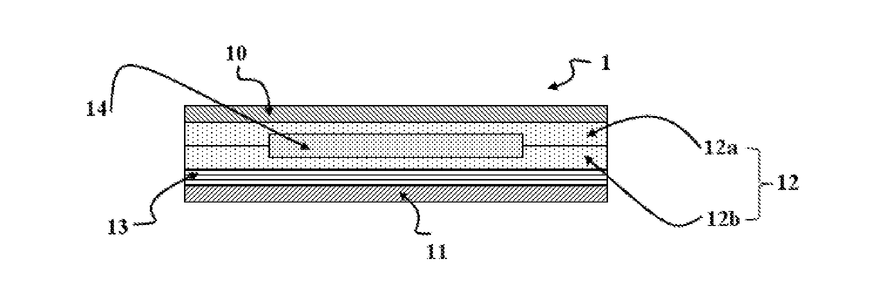
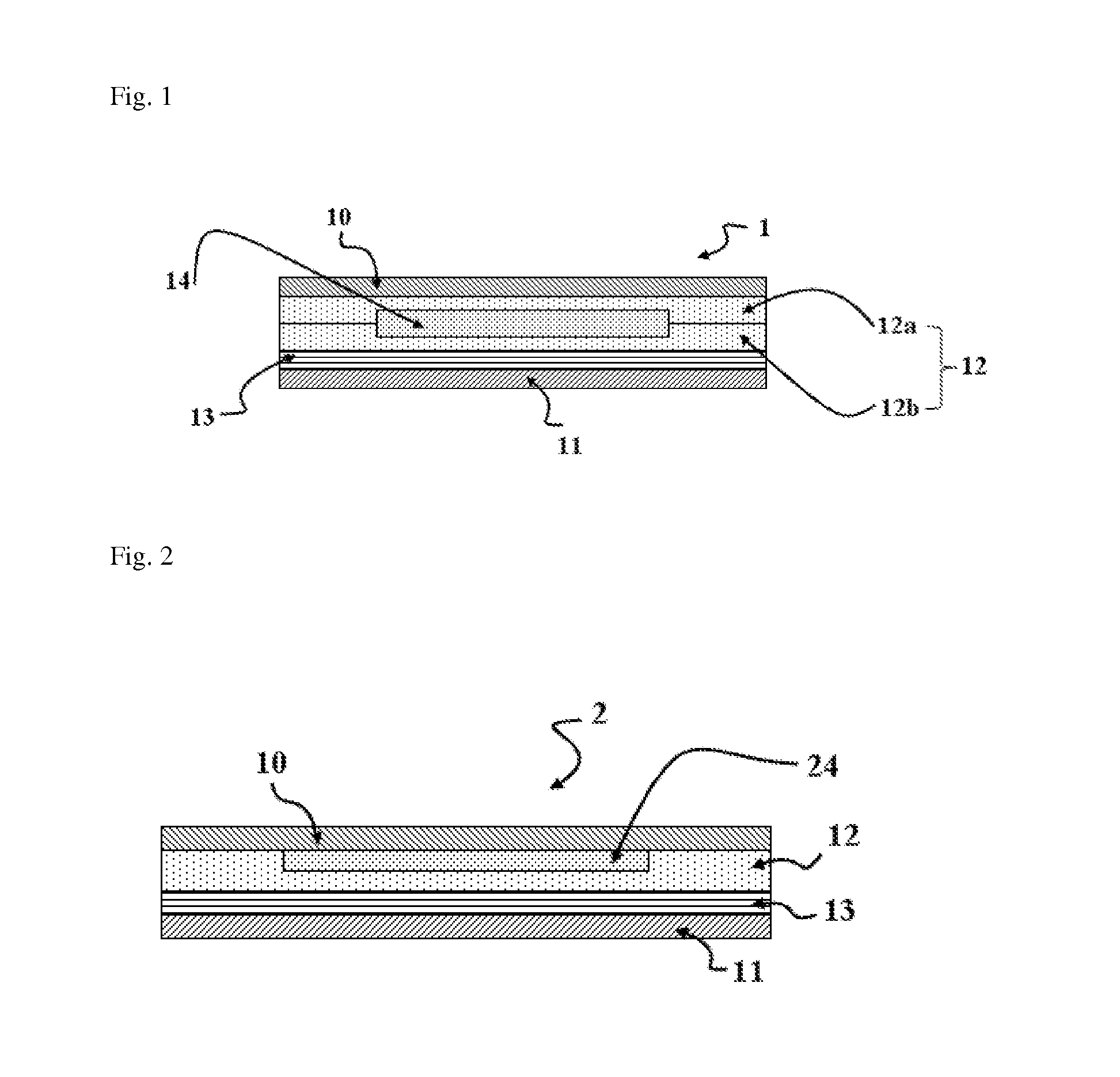
Photovoltaic cell module
a photovoltaic cell and module technology, applied in the field of photovoltaic cell modules, can solve the problems of brittle wafer-based photovoltaic cells and thin film photovoltaic cells, low adhesive strength of conventional encapsulants made of eva-based materials or the like, and low adhesive strength of conventional encapsulants to glass and other parts of the modules, so as to prevent the separation of the layer constituting the module, the effect of excellent power generation efficiency and excellent durability
- Summary
- Abstract
- Description
- Claims
- Application Information
AI Technical Summary
Benefits of technology
Problems solved by technology
Method used
Image

Examples
preparation example 2
Preparation of Encapsulant Composition (2)
[0089]100 g of a polymer compound having a resin structure represented by (ViMe2SiO1 / 2)2(ViMeSiO2 / 2)5(Ph2SiO2 / 2)20(Me2SiO2 / 2)40, 3 g of a polymer compound having a resin structure represented by (ViMe2SiO1 / 2)2(MeEpSiO2 / 2)5(Ph2SiO2 / 2)10(Me2SiO2 / 2)10, 50 g of a polymer compound having a resin structure represented by (ViMe2SiO1 / 2)2.5(PhSiO3 / 2)7, and 20 g of a polymer compound having a resin structure represented by (HMe2SiO1 / 2)2(Ph2SiO2 / 2)1.5 were mixed and a platinum(0)-1,3-divinyl-1,1,3,3-tetramethyldisiloxane solution was added thereto as a platinum-based catalyst such that the amount of Pt(0) could be 10 ppm and 20 g of TiO2 particles having an average diameter of 3,000 nm was added. Thus, an encapsulant composition (2) was prepared.
preparation example 3
Preparation of Encapsulant Composition (3)
[0090]100 g of a polymer compound having a resin structure represented by (ViMe2SiO1 / 2)2(Ph2SiO2 / 2)10(Me2SiO2 / 2)40, 3 g of a polymer compound having a resin structure represented by (ViMe2SiO1 / 2)2(MeEpSiO2 / 2)5(Ph2SiO2 / 2)10(Me2SiO2 / 2)10, 50 g of a polymer compound having a resin structure represented by (ViMe2SiO1 / 2)2(Me2SiO2 / 2)5(PhSiO3 / 2)7, and 30 g of a polymer compound having a resin structure represented by (HMe2SiO1 / 2)2(PhMeSiO2 / 2)1.5 were mixed and a platinum(0)-1,3-divinyl-1,1,3-tetramethyldisiloxane solution was added thereto as a platinum-based catalyst such that the amount of Pt(0) could be 5 ppm. Thus, an encapsulant composition (3) was prepared.
preparation example 4
Preparation of Encapsulant Composition (4)
[0091]100 g of a polymer compound having a resin structure represented by (ViMe2SiO1 / 2)2(Ph2SiO2 / 2)10(Me2SiO2 / 2)40, 3 g of a polymer compound having a resin structure represented by (ViMe2SiO1 / 2)2(MeEpSiO2 / 2)5(Ph2SiO2 / 2)10(Me2SiO2 / 2)10, 50 g of a polymer compound having a resin structure represented by (ViMe2SiO1 / 2)2(Me2SiO2 / 2)5(PhSiO3 / 2)7, and 30 g of a polymer compound having a resin structure represented by (HMe2SiO1 / 2)2(PhMeSiO2 / 2)1.5 were mixed and a platinum(0)-1,3-divinyl-1,1,3-tetramethyldisiloxane solution a was added thereto s a platinum-based catalyst such that the amount of Pt(0) could be 5 ppm and 20 g of TiO2 particles having an average diameter of 3,000 nm was added. Thus, an encapsulant composition (4) was prepared.
PUM
| Property | Measurement | Unit |
|---|---|---|
| Percent by mass | aaaaa | aaaaa |
| Percent by mass | aaaaa | aaaaa |
| Percent by mass | aaaaa | aaaaa |
Abstract
Description
Claims
Application Information