Supercharge Your Innovation With Domain-Expert AI Agents!

Voltage doubler and oscillating control signal generator thereof

a voltage doubler and oscillating control technology, applied in the direction of power conversion systems, instruments, frequency change manipulation, etc., can solve the problems of affecting the efficiency, the difficulty of timely switching the frequency of the oscillating control signal without affecting the efficiency, and the effect of the voltage doubler

Active Publication Date: 2013-11-21
NAN YA TECH
View PDF2 Cites 1 Cited by
  • Summary
  • Abstract
  • Description
  • Claims
  • Application Information

AI Technical Summary

Benefits of technology

The patent describes a voltage douler and a circuit that generates an oscillating control signal. The voltage douler consists of a charge pump, a comparator, and a fundamental oscillation signal generator. The charge pump controls the second voltage provided to the comparator, which compares it to a target value to generate the fundamental oscillation signal. An oscillating control signal is generated based on the comparison result and the electric current consumption status of the charge pump. The logic circuit selectively blocks changes in the fundamental oscillation signal based on the comparison result and electric current consumption status. The technical effect of the invention is to provide a more reliable and efficient control of the charge pump.

Problems solved by technology

However, by the multiplexing design, it is difficult to timely switch the frequency of the oscillating control signal without affecting the efficiency of the voltage doubler. FIG. 1 shows a multiplexing design, which outputs an oscillating control signal fxc selected from the oscillation signals fx1 and fx2.
However, a glitch occurs due to PVT variations, which affects the efficiency of the voltage doubler.

Method used


Image

  • Voltage doubler and oscillating control signal generator thereof
  • Voltage doubler and oscillating control signal generator thereof
  • Voltage doubler and oscillating control signal generator thereof

Examples


Embodiment Construction

[0022]The following description shows several exemplary embodiments carrying out the invention. This description is made for the purpose of illustrating the general principles of the invention and should not be taken in a limiting sense. The scope of the invention is best determined by reference to the appended claims.

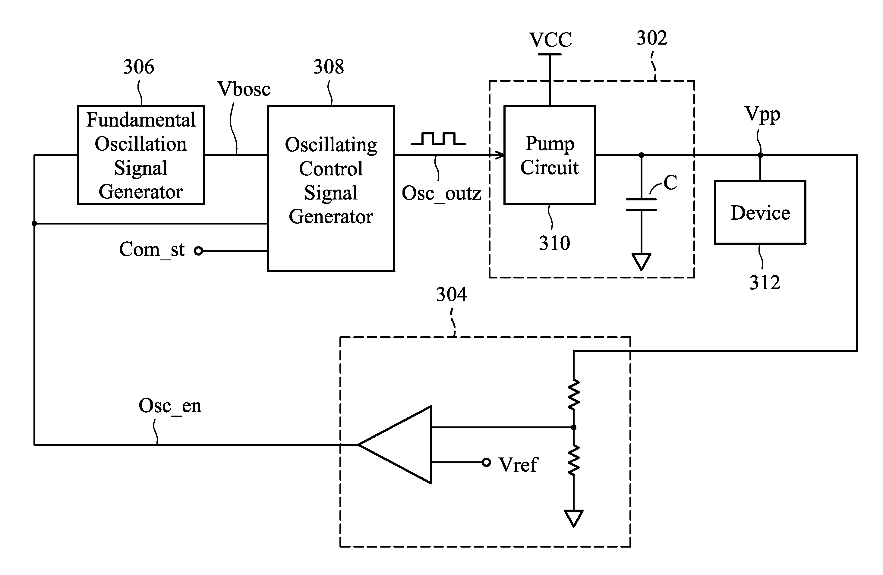
[0023]FIG. 3 depicts a voltage doubler in accordance with an exemplary embodiment of the invention. As shown, a voltage doubler comprises a charge pump 302, a comparator 304, a fundamental oscillation signal generator 306 and an oscillating control signal generator 308.

[0024]The charge pump 302 is powered by a first voltage Vcc and has a capacitor C as an energy storage element. The capacitor C is pumped by a pump circuit 310. An oscillating control signal Osc_outz is sent to the pump circuit 310 to pump the capacitor C according to the oscillation of the oscillating control signal Osc_outz and thereby to control a second voltage Vpp provided by the capacitor C. The se...


PUM


Abstract

A voltage doubler and an oscillating control signal generator controlling a charge pump (powered by a first voltage to provide a second voltage) of the voltage doubler are disclosed. The oscillating control signal generator includes a first input terminal receiving a fundamental oscillation signal, a second input terminal receiving a comparison result showing whether the second voltage is greater than a target value, a third input terminal operative to obtain an electric current consumption status at an output terminal of the charge pump, and an output terminal outputting an oscillating control signal for the control of the charge pump. Further, the oscillating control signal generator includes a logic circuit. The logic circuit generates the oscillating control signal by selectively blocking status changes of the fundamental oscillation signal according to the comparison result and the electric current consumption status.

Description

BACKGROUND OF THE INVENTION[0001]1. Field of the Invention[0002]The present invention relates to voltage doublers, and in particular relates to oscillating control signal generators thereof.[0003]2. Description of the Related Art[0004]A voltage doubler is commonly used to generate a voltage at a level higher than the supply voltage (not limited to twice of the supply voltage). In this manner, the generated voltage can be used in powering a device which has to be operated by a voltage higher than the supply voltage. For example, an LED driver, an LCD driver, a memory (e.g. DRAM, SRAM) and so on may require a voltage doubler.[0005]In conventional techniques, a charge pump may be used to implement the voltage doubler. A charge pump may use a capacitor as a power storage element. According to an oscillating control signal, the charge pump charges the capacitor to provide a voltage at a level higher than the supply voltage. The charging of the capacitor depends on the frequency of the os...

Claims


Application Information

Patent Timeline
IPC IPC(8): G05F1/10
CPCH02M3/07H03K5/00006H02M1/0003
Inventor CHAO, KUANG-WEI
Owner NAN YA TECH
Features
  • R&D
  • Intellectual Property
  • Life Sciences
  • Materials
  • Tech Scout
  • Unparalleled Data Quality
  • Higher Quality Content
  • 60% Fewer Hallucinations
Learn More