Balanced antenna system

a technology of balanced antennas and balanced antennas, applied in the field of balanced antenna systems, can solve the problems of few portable devices with mimo systems on the market, currently considered difficult (or perhaps even impossible) to implement such structures at lower frequencies, and achieve wide frequency tuning range, wideband performance, and wide tuneable range

Active Publication Date: 2013-11-21
SMART ANTENNA TECH
View PDF8 Cites 73 Cited by
  • Summary
  • Abstract
  • Description
  • Claims
  • Application Information

AI Technical Summary

Benefits of technology

[0058]It will be understood that a merit of employing a further antenna as described above is that it enables those knowledgeable in the art to easily configure the antenna to a multitude of operating frequencies. Furthermore, various impedance-matching circuit configurations can be easily implemented to enable the further antenna to operate in both a listening and an application mode. Thus, the further antenna design described above can provide a wide frequency tuning range or wideband performance. However, it cannot provide MIMO performance on its own as there is a strong coupling between the two ports when they are at the same frequency. Even at relatively low frequencies (e.g. 700 MHz), simulation results have shown that the coupling is approximately zero, however, it noted that for a product suitable for mobile phone applications, a couplin

Problems solved by technology

However, there are very few portable devices with MIMO systems on the market and this is mainly because of the complications around gathering several radiators in a small device (due to the small allocated space of the terminal), while maintaining the required isolat

Method used


Image

  • Balanced antenna system
  • Balanced antenna system
  • Balanced antenna system

Examples


Embodiment Construction

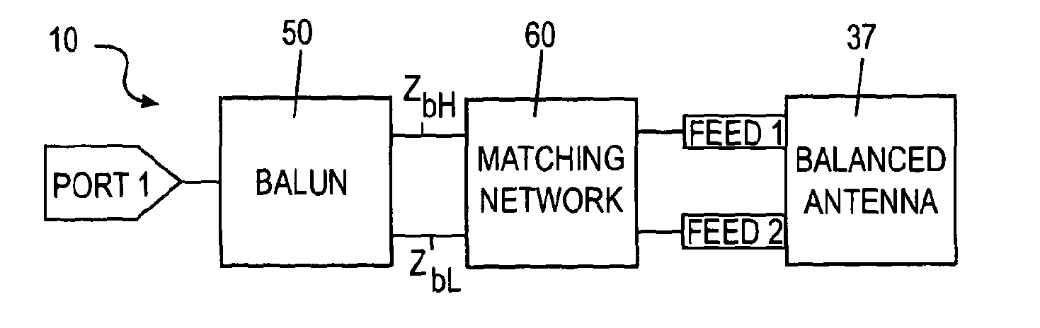
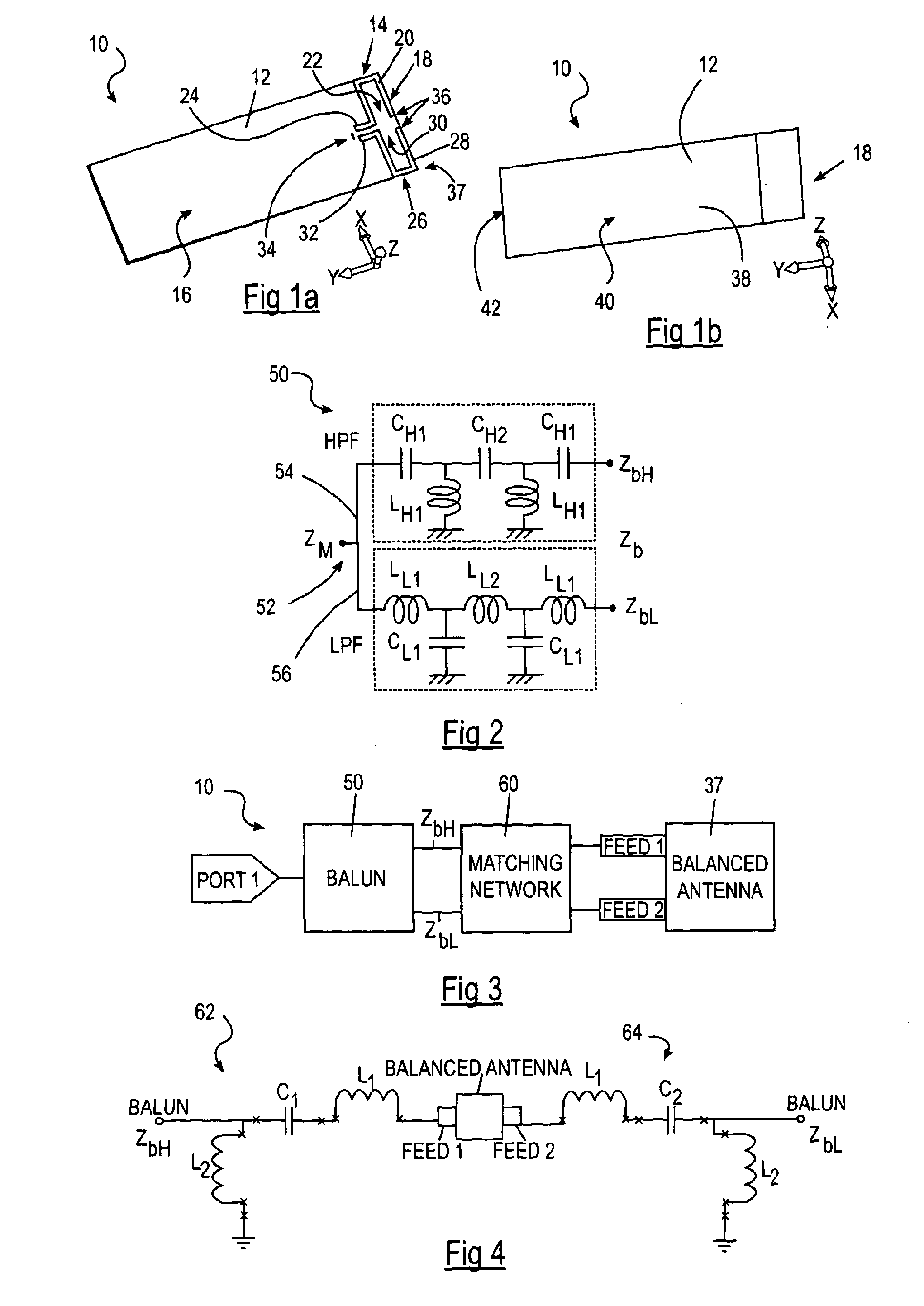
[0111]With reference to FIGS. 1A and 1B, there is illustrated a balanced antenna system 10 according to a first embodiment of the present invention. The balanced antenna system 10 is reconfigurable, as will be described in more detail below, and is designed for use in a portable product such as a mobile phone, laptop or PDA.

[0112]The balanced antenna system 10 is provided on a microwave substrate 12 (e.g. a printed circuit board, PCB) having a surface area of approximately 116×40 mm2 and a thickness of approximately 1.15 mm so that the system can easily be accommodated in a conventional mobile phone.

[0113]As illustrated in FIG. 1A, a first radiating element 14 is provided on a first side 16 of the substrate 12, at a first end portion 18 thereof. The first radiating element 14 is formed from a substantially U-shaped first strip layer 20 which is located in one half of the first end portion 18 of the substrate 12 and is orientated such that its open end 22 faces inwardly towards the c...


PUM


Abstract

The invention relates to a balanced antenna system comprising a radiator connected via a matching circuit to a balun. In certain embodiments, the radiator comprises a first radiating element and a second radiating element and the matching circuit comprises a first impedance-matching circuit connected to the first radiating element and a second impedance-matching circuit connected to the second radiating element. The first and second matching circuits may be identical and are connected through the balun to a single port. To minimise the component count, the design of the matching circuit and balun is co-optimised.

Description

FIELD OF THE INVENTION[0001]The invention relates to a balanced antenna system. Particularly, but not exclusively, the invention relates to a balanced antenna system for use in a portable electronic device such as a mobile telephone, laptop, personal digital assistant (PDA) or radio.BACKGROUND TO THE INVENTION[0002]Multiple-input-multiple-output (MIMO) wireless systems exploiting multiple antennas for transmitting and / or receiving data have attracted increasing interest due to their potential for increased capacity in rich multipath environments. Such systems can be used to enable enhanced communication performance (i.e. improved signal quality and reliability) by use of multi-path propagation without requiring additional spectrum bandwidth. This has been a well-known and well-used solution to achieve high data rate communications employing either 2G or 3G communication standards.[0003]For indoor wireless applications such as router devices, external dipole and monopole antennas are...

Claims


Application Information

Patent Timeline
IPC IPC(8): H01Q1/50H01Q21/00
CPCH01Q1/50H01Q21/0006H01Q1/243H01Q1/521H01Q9/265H01Q21/28H03H7/38H03H7/42H03H7/465H01Q1/24H01Q1/52H01Q9/26H03H7/46H01Q5/335
Inventor HU, ZHEN HUA SAMPSONHALL, PETER
Owner SMART ANTENNA TECH
Why Eureka
Try Eureka