
Depression-provided steel pipe and composite pile

a technology of compression-provided steel pipe and composite pile, which is applied in the direction of liquid surface applicators, coatings, constructions, etc., can solve problems such as uneconomical design, and achieve the effects of improving adhesive force, increasing adhesive force, and improving adhesive for

Inactive Publication Date: 2013-11-21
NIPPON STEEL CORP
View PDF11 Cites 7 Cited by
  • Summary
  • Abstract
  • Description
  • Claims
  • Application Information

AI Technical Summary

Benefits of technology

The invention describes a method for improving the adhesive force between a steel pipe and a solidified material, such as cement, by arranging multiple depressed portions on the outer surface of the steel pipe. These depressed portions form a line along the axial direction of the steel pipe, increasing the area where the solidified material adheres to the pipe. Additionally, a columnar groove is formed in each depressed portion, creating a frictional force or shearing force at the interface between the solidified material and the surrounding material, which prevents slipping. By setting the hardness of the steel pipe and adding a mill scale covering the depressed portions, the compressive strength of the steel pipe is maintained. The percentage of the depressed portions in the circumferential direction of the steel pipe is set to 50% or less to avoid buckling. The depressed portions are arranged in parallel lines or with a phase difference of not less than ⅛ and not more than ½ to ensure uniform adhesive force and compressive strength. The number of depressed portions is set to six or more to achieve even better results. Overall, this method improves the adhesive force between the steel pipe and the solidified material without compromising the compressive strength of the steel pipe.

Problems solved by technology

Thus, in the case where the ground is weak or the supporting layer is located deeply in the ground, the size of the pile needs to be increased, resulting in uneconomical design.

Method used


Image

  • Depression-provided steel pipe and composite pile
  • Depression-provided steel pipe and composite pile
  • Depression-provided steel pipe and composite pile

Examples


first embodiment

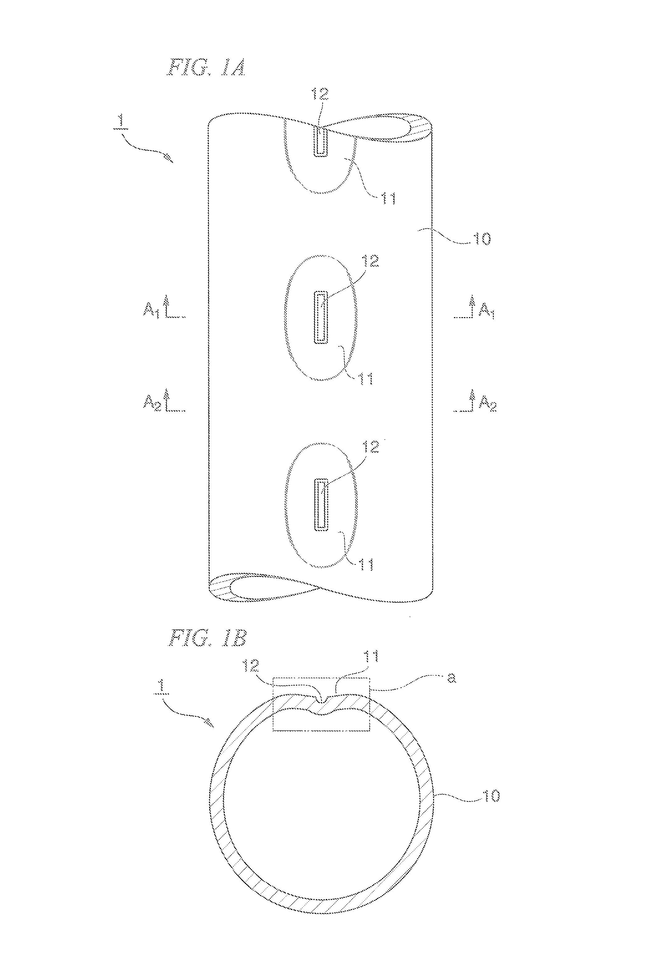
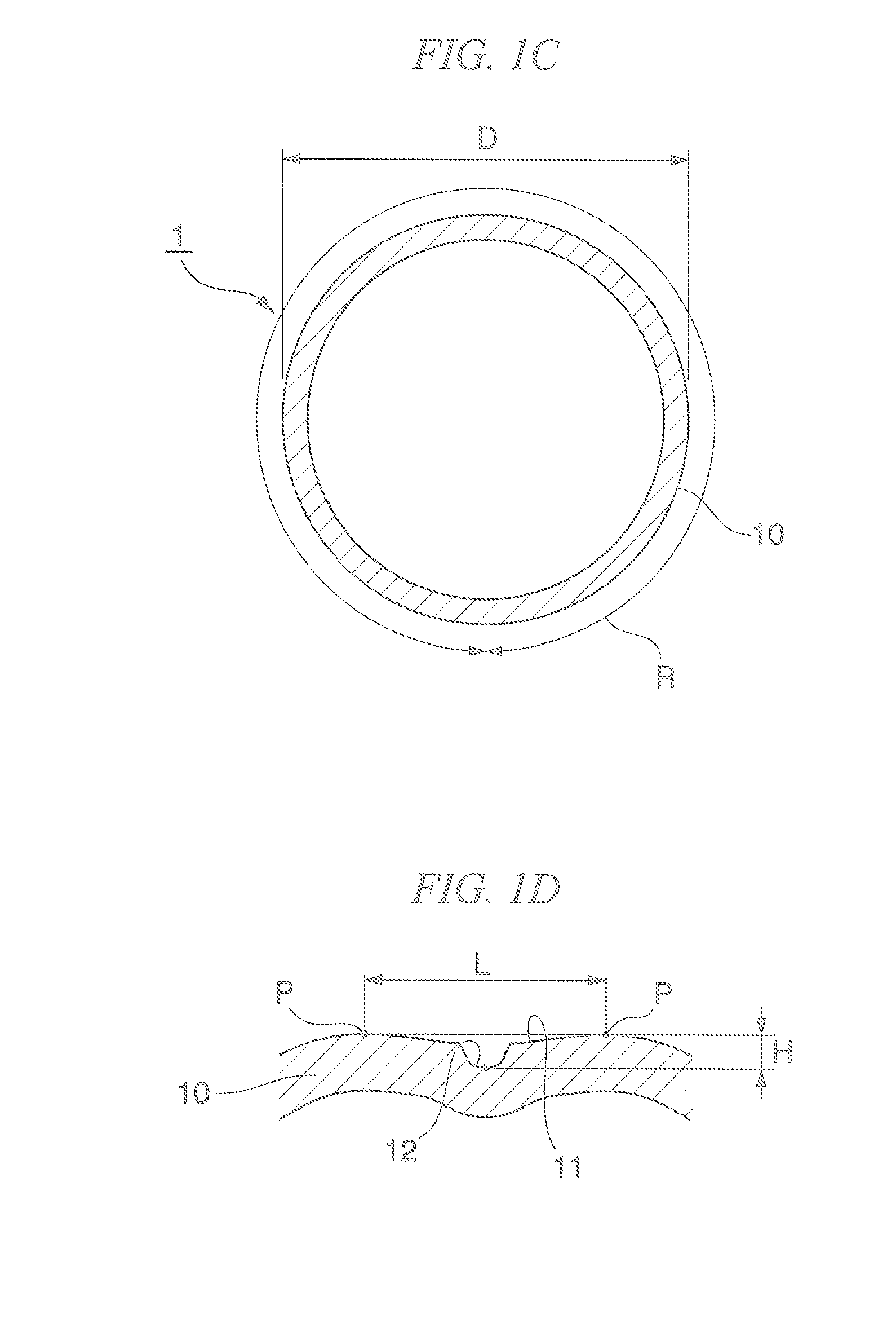
[0043]Below, with reference to FIG. 1A to FIG. 1D, a depression-provided steel pipe 1 according to a first embodiment of the present invention will be described.

[0044]FIG. 1A is a front view partially illustrating the depression-provided steel pipe 1 according to the first embodiment of the present invention. The depression-provided steel pipe 1 extends in the axial direction of the steel pipe so as to have a predetermined length, and for the purpose of explanation, part of the depression-provided steel pipe 1 is illustrated in FIG. 1A.

[0045]As illustrated in FIG. 1A, the depression-provided steel pipe 1 according to the first embodiment of the present invention is formed by a steel pipe body 10 having a substantially tubular shape. On the outer peripheral surface of this steel pipe body 10, plural depressed portions 11 are formed. Further, a columnar groove portion 12 is formed at the center of each of the depressed portions 11.

[0046]As illustrated in FIG. 1A, the plural depressed ...

second embodiment

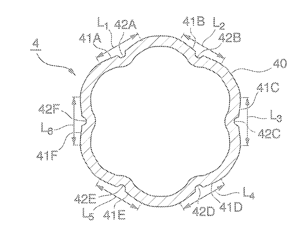
[0064]Below, with reference to FIG. 2A and FIG. 2B, a depression-provided steel pipe 2 according to a second embodiment of the present invention will be described. The depression-provided steel pipe 2 according to this embodiment is different from the depression-provided steel pipe 1 according to the first embodiment in that four lines of the depressed portions are provided in this embodiment.

[0065]FIG. 2A is a front view partially illustrating the depression-provided steel pipe 2 according to the second embodiment of the present invention. The depression-provided steel pipe 2 extends in the axial direction of the steel pipe so as to have a predetermined length, and for the purpose of explanation, part of the depression-provided steel pipe 2 is illustrated in FIG. 2A.

[0066]As illustrated in FIG. 2A, the depression-provided steel pipe 2 according to the second embodiment of the present invention is formed by a steel pipe body 20 having a substantially tubular shape. On the outer peri...

third embodiment

[0083]Below, with reference to FIG. 3A and FIG. 3B, a depression-provided steel pipe 3 according to the third embodiment of the present invention will be described. The depression-provided steel pipe 3 according to this embodiment is different from the depression-provided steel pipe 2 according to the second embodiment in that lines of the depressed portions adjacent in the circumferential direction of the steel pipe are provided so as to have a phase difference in the axial direction of the steel pipe in this embodiment. Elements that have been already explained will not be repeated.

[0084]FIG. 3A is a front view partially illustrating the depression-provided steel pipe 3 according to the third embodiment of the present invention. The depression-provided steel pipe 3 extends in the axial direction of the steel pipe so as to have a predetermined length, and for the purpose of explanation, part of the depression-provided steel pipe 3 is illustrated in FIG. 3A.

[0085]As illustrated in F...


PUM

PropertyMeasurementUnit
temperaturesaaaaaaaaaa
thicknessaaaaaaaaaa
lengthaaaaaaaaaa

Abstract

This depression-provided steel pipe has plural depressions on an outer peripheral surface, the depressions being formed so as to form a line along an axial direction of the steel pipe, in which each of the depressed portions has, inside thereof, a columnar groove portion extending along the axial direction of the steel pipe and depressed deeper than a bottom surface of these depressed portions; 0.95≦HA / HB≦1.05 is satisfied, where HA is an average Vickers hardness in each of the depressed portions, and HB is a Vickers hardness at a portion between the depressed portions adjacent to each other in the axial direction of the steel pipe; and the outer peripheral surface is covered with a mill scale.

Description

TECHNICAL FIELD[0001]The present invention relates to a depression-provided steel pipe and a composite pile used for forming a civil engineering and construction structure.[0002]The present application claims priority based on Japanese Patent Application No. 2011-035535 filed in Japan on Feb. 22, 2011, the disclosures of which are incorporated herein by reference in their entirety.BACKGROUND ART[0003]Piles used as foundation for civil engineering and construction structures achieve a supporting force derived from an end supporting force and a frictional force on the outer peripheral surface. The end supporting force is a bearing pressure resistance occurring at an end portion of the pile, which is driven into hard ground to obtain a large supporting force. The frictional force on the outer peripheral surface occurs from a frictional force between the pile and the ground. In general, the frictional force on the outer peripheral surface occurring between the steel pipe pile and the gr...

Claims


Application Information

Patent Timeline
Patent Type & Authority Applications(United States)
IPC IPC(8): E02D5/28
CPCE02D5/285B21C37/158B21D15/00B21D17/02B21D17/04E02D5/28E02D5/30
Inventor TAKAGI, MASAHIDETAENAKA, SHINJISATOH, TETSUMOTEGI, YUKIOOSAWA, TAKASHI
Owner NIPPON STEEL CORP
Learn More