
Method and apparatus for thermoacoustic cooling

a technology of thermoacoustic cooling and apparatus, applied in the direction of gas cycle refrigeration machines, cooling/ventilation/heating modifications, compression machines, etc., can solve the problems of device failure, device failure to pass the thermal limit, and particularly substantive switching losses

Inactive Publication Date: 2013-11-28
NOKIA TECHNOLOGLES OY
View PDF7 Cites 25 Cited by
  • Summary
  • Abstract
  • Description
  • Claims
  • Application Information

AI Technical Summary

Benefits of technology

The present invention provides an apparatus and method for cooling electronic devices using thermoacoustic cooling. The apparatus includes a transducer, a cavity, and a thermodynamic member that exchanges heat with the cavity gas or fluid. The transducer generates a standing wave within the cavity to transfer heat along the thermodynamic member. The apparatus can be used in electronic devices to prevent heating issues.

Problems solved by technology

These switching losses are particularly substantive in modern integrated circuit processors where the clocking frequencies are high.
For example passive heat dissipation in mobile devices such as phones can use expensive heat spreader tapes which attempt to conduct heat from the heat generator, or where there is sufficient volume heat pipes which carry out a similar conductive process of heat away from the potential hot spot but which require a significant volume for a small device.
However these are expensive and cannot be used without some circulatory system to recycle the heat.
Whilst the use of fans in desktop or large equipment is acceptable, the use of fans in mobile devices is problematic in that they typically require a relatively large volume, can be acoustically noisy, and can be prone to failure causing the device to pass the thermal limit and fail.
Where the component density is even higher or frequencies suitably high even forced air cooling may not be sufficient and cooled liquid or water cooling can be used.
However liquid cooling further has inherent disadvantages when used in electronic apparatus in that it is typically heavy, requires ever more volume to implement, and can cause water vapour to condense on electronic components causing them to fail.
For these reasons, forced air and water cooled systems are typically not implemented in portable devices and mobile devices but used in larger devices such as desktop computers.

Method used


Image

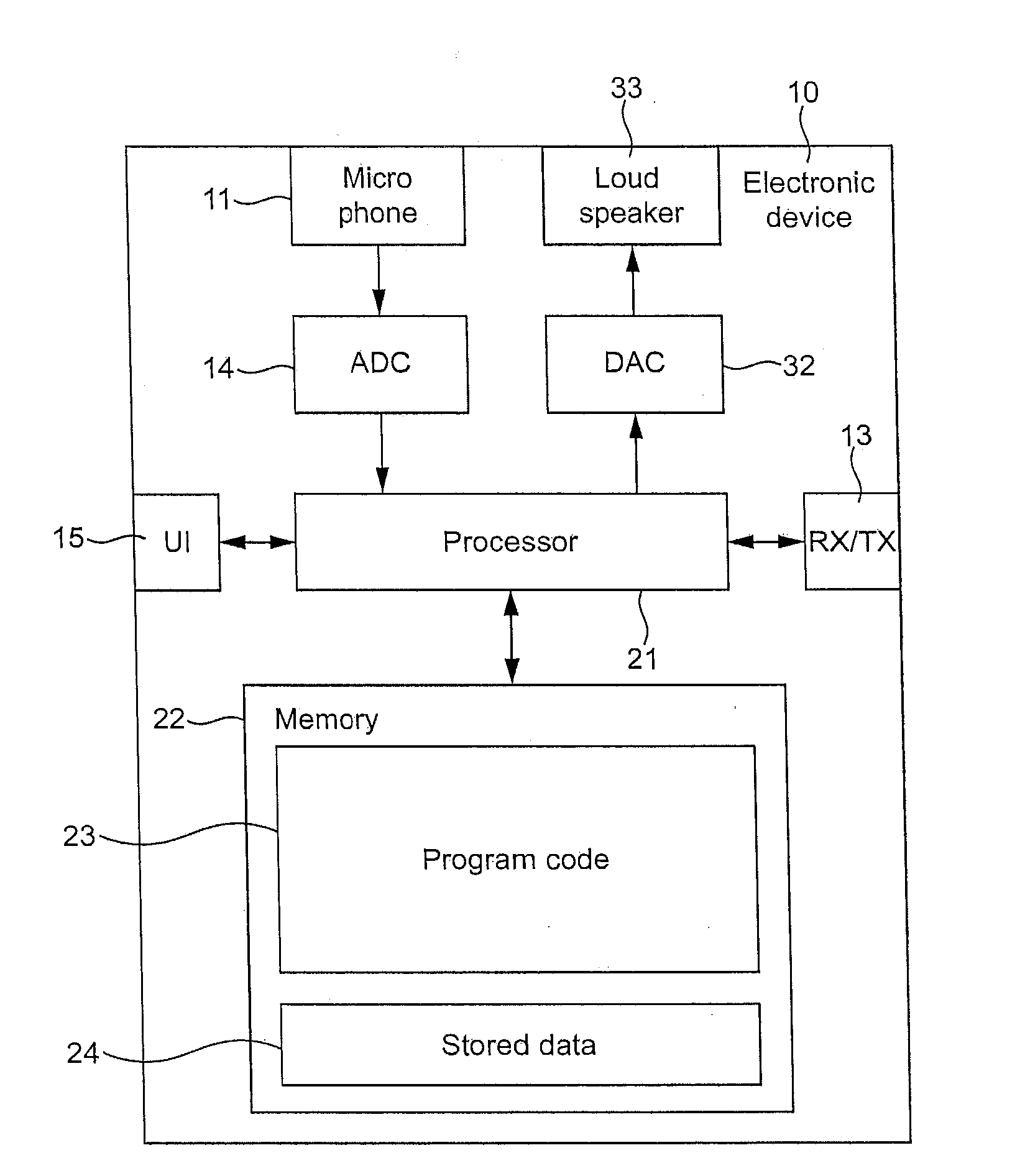
  • Method and apparatus for thermoacoustic cooling
  • Method and apparatus for thermoacoustic cooling
  • Method and apparatus for thermoacoustic cooling

Examples


Embodiment Construction

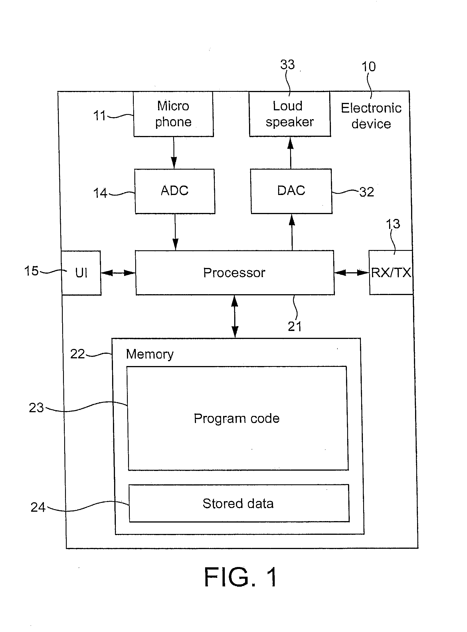
[0009]Embodiments of the present invention attempt to overcome heating issues by implementing thermoacoustic cooling apparatus within electronic devices.

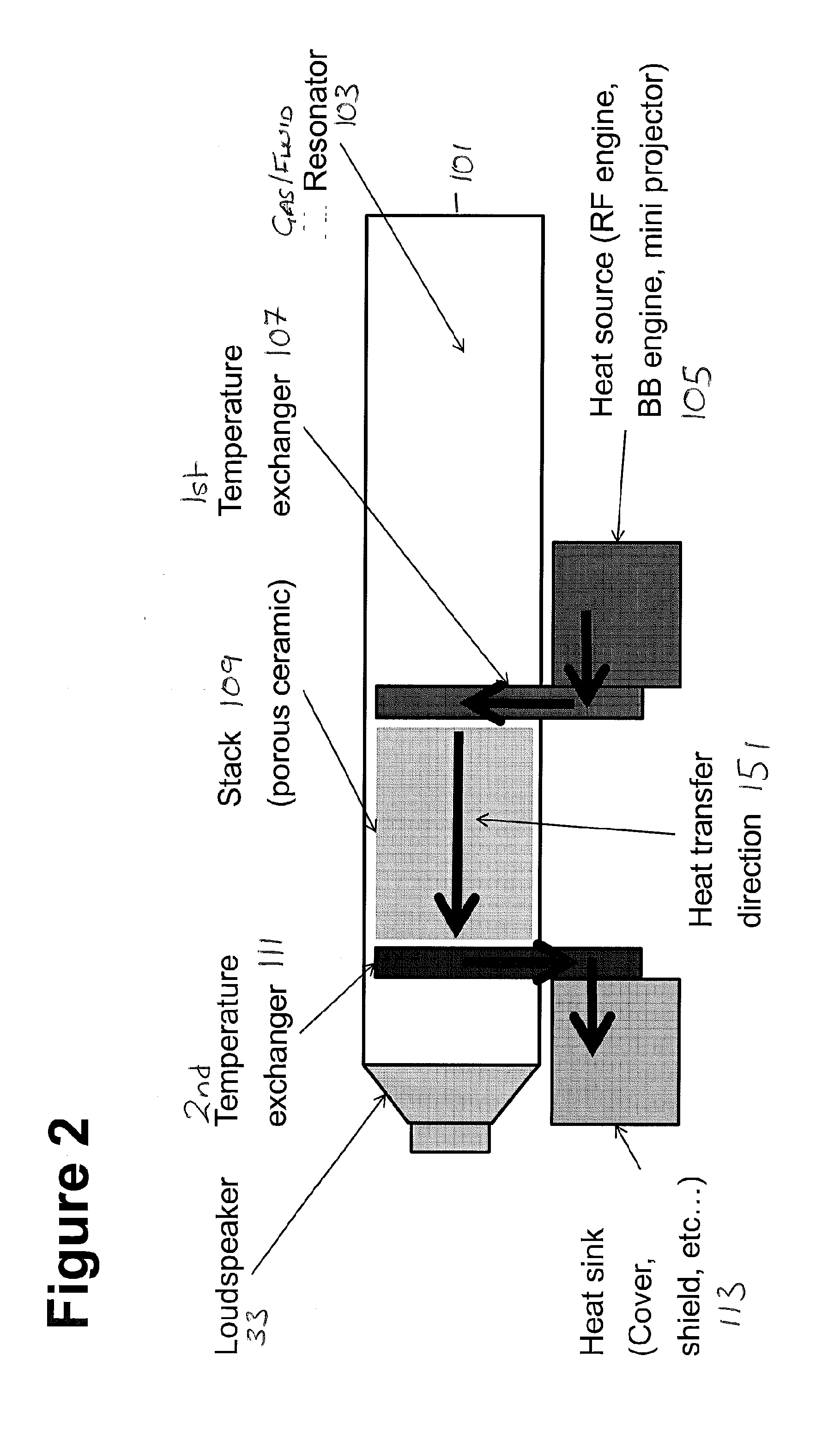
[0010]There is provided according to an aspect of the application an apparatus comprising: at least one transducer comprising a displacement component that is configured to move upon application of an electrical signal; a cavity in communication with the at least one transducer; and at least one thermodynamic member within the cavity configured to readily exchange heat with a cavity gas or fluid, wherein the transducer is configured to generate a standing wave within the cavity to transfer heat along the thermodynamic member.

[0011]The thermodynamic member may comprise a substrate.

[0012]The substrate may comprise at least one of: at least two layers of thermodynamic material; and at least two tubes of the thermodynamic material.

[0013]The cavity may be substantially sealed at least at one end.

[0014]The apparatus may further comprise a...


PUM


Abstract

Apparatus comprising at least one transducer comprising a displacement component that is configured to move upon application of an electrical signal; a cavity in communication with the at least one transducer; and at least one thermodynamic member within the cavity configured to readily exchange heat with a cavity gas or fluid, wherein the transducer is configured to generate a standing wave within the cavity to transfer heat along the thermodynamic member.

Description

FIELD OF THE APPLICATION[0001]The present invention relates to thermoacoustic cooling apparatus. The invention further relates to, but is not limited to, thermoacoustic cooling apparatus for mobile devices.BACKGROUND OF THE APPLICATION[0002]Electronic components in real world applications generate heat when in operation. For example components can have resistive losses such as found in coils in transducers and transistors have transistor switching losses where electrical energy is converted into heat during every switch state change. These switching losses are particularly substantive in modern integrated circuit processors where the clocking frequencies are high.[0003]Typical heat generators in mobile devices can be, for example the radio frequency engine (in other words the radio frequency transceiver components), the baseband engine (in other words the processors controlling the coding and decoding of the data signals, such as the audio data), transducers (such as the speaker), a...

Claims


Application Information

Patent Timeline
IPC IPC(8): H05K7/20
CPCH05K7/20F25B9/14F25B2309/1403
Inventor GREUET, JEAN-BAPTISTECIESLAK, LARS
Owner NOKIA TECHNOLOGLES OY
Learn More