
Rich-lean burner

a burner and rich-lean technology, applied in the direction of burners, staged combustion, combustion types, etc., can solve the problems of inability to achieve stable combustion and inability to increase and achieve the effect of increasing the surface area of the lean gas flame, stable combustion, and reliably increasing the surface area of the flam

Active Publication Date: 2013-11-28
PALOMA
View PDF29 Cites 10 Cited by
  • Summary
  • Abstract
  • Description
  • Claims
  • Application Information

AI Technical Summary

Benefits of technology

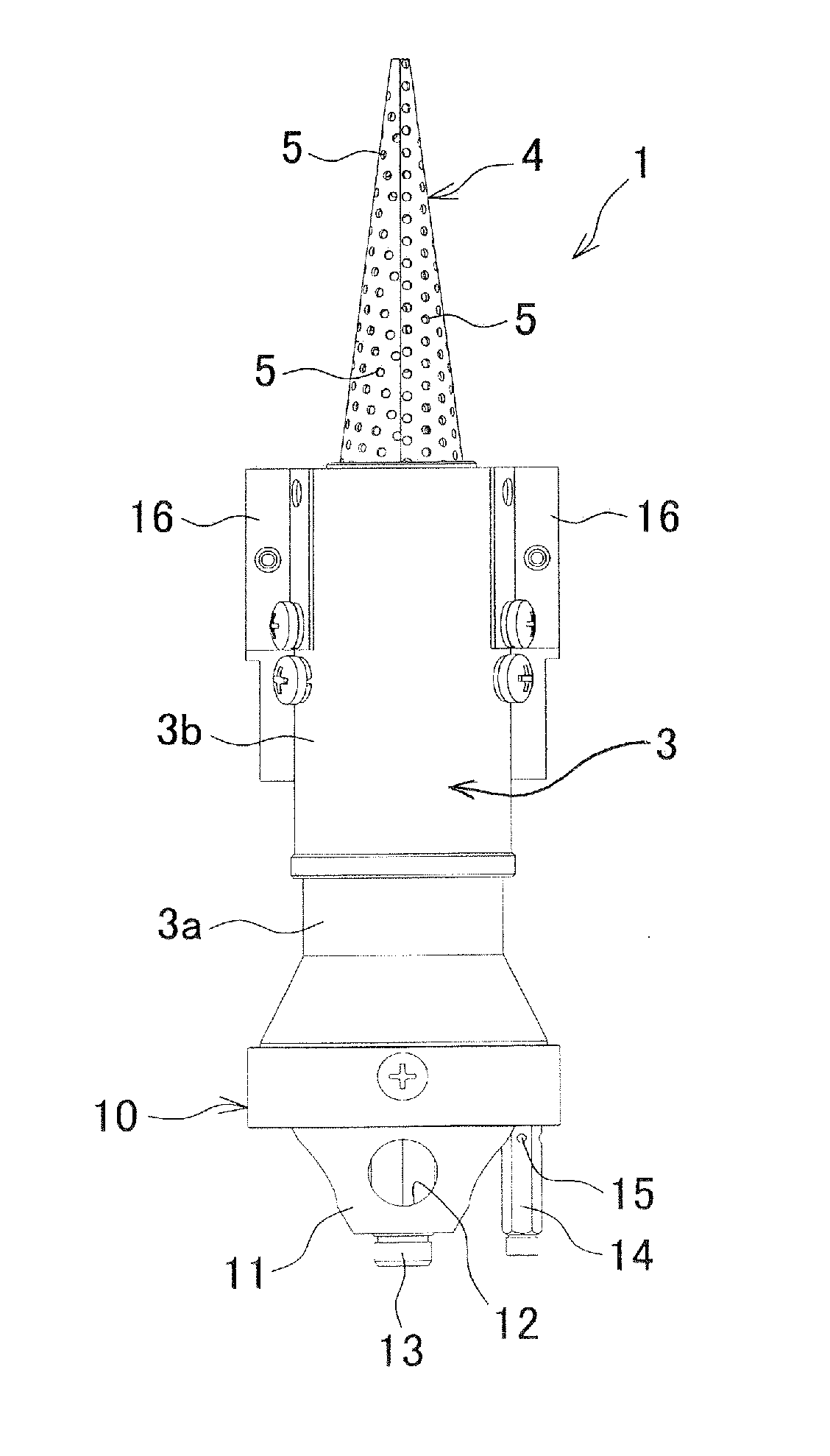
The present invention provides a rich-lean burner that can achieve stable combustion by increasing a flame surface area. This is achieved by reliably increasing the surface area of lean gas flames formed on the surface of the protruding body, and also by increasing the stability of the lean gas flames by forming a flame of the lean gas, whose flow rate is lower than that of the lean gas blown out from the small holes, at the base of the protruding body.

Problems solved by technology

Therefore, a flame surface area cannot be increased by increasing the total area of the lean flame hole, and stable combustion is not achieved.

Method used


Image

  • Rich-lean burner
  • Rich-lean burner
  • Rich-lean burner

Examples


Embodiment Construction

[0020]Hereinafter, an embodiment of the present invention will be explained with reference to the drawings.

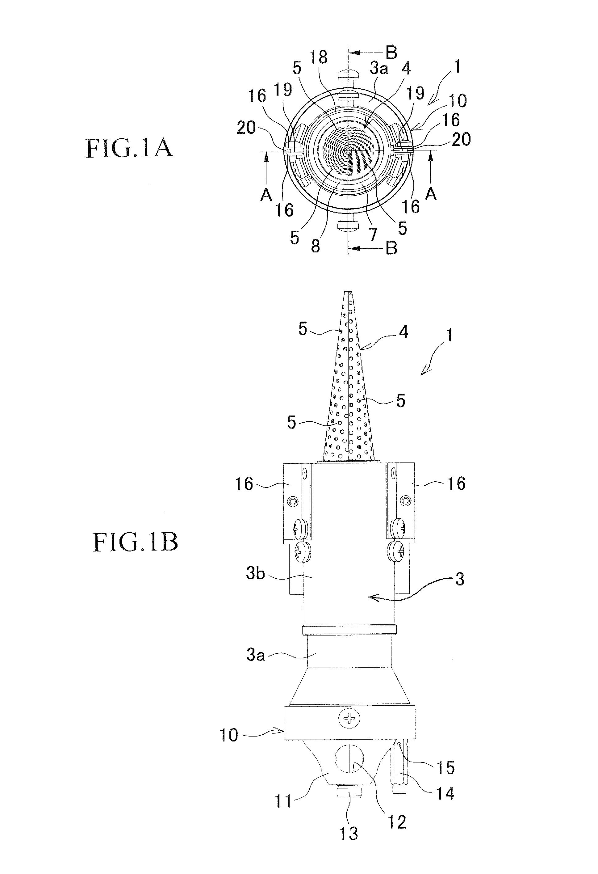
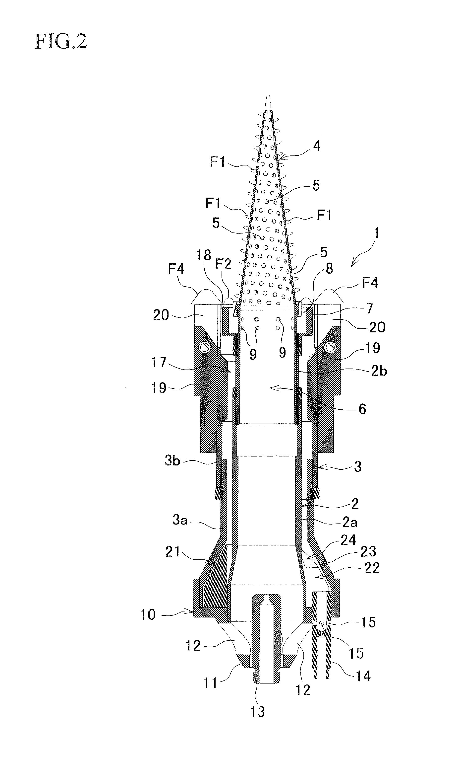
[0021]FIG. 1 is an explanatory diagram showing an example of a rich-lean burner 1, and (A) shows a plane surface and (B) shows a front surface. FIG. 2 shows a cross section taken along a line A-A in FIG. I, and FIG. 3 shows a cross section taken along a line B-B in FIG. 1.

[0022]The rich-lean burner 1 has a double tube structure, and includes an inner cylinder 2 and an outer cylinder 3 that is coaxially disposed around the inner cylinder 2.

[0023]First, the inner cylinder 2 includes a lower inner cylinder 2a and an upper inner cylinder 2b that is coaxially inserted into the lower inner cylinder 2a. A conical burner head 4, which is a protruding body, is coaxially fitted into an upper end opening of the upper inner cylinder 2b. The burner head 4 is made of a perforated metal, in which a plurality of small holes (lean flame holes) 5 are arranged in a zigzag manner, into a conical s...


PUM


Abstract

A rich-lean burner includes an inner cylinder to which lean gas, which is a mixture of gas and combustion air, is supplied, and an outer cylinder that is coaxially disposed around the inner cylinder such that rich gas, which is a mixture of gas and combustion air, is supplied between the inner cylinder and the outer cylinder. A burner head, which has small holes and whose diameter decreases toward the leading end, is provided on an opening of the inner cylinder. The burner head is obtained by forming a perforated metal, in which the small holes are arranged in a zigzag manner, into a conical shape. An interval between each of the small holes is two to three times the diameter of the small holes. The total area of the small holes is larger than the area of an upper end opening of an upper inner cylinder.

Description

BACKGROUND OF THE INVENTION[0001]This application claims the benefit of Japanese Patent Application Number 2012-117824 filed on May 23, 2012, the entirety of which is incorporated by reference.TECHNICAL FIELD[0002]The present invention relates to a rich-lean (off-stoichiometric) burner (a low NOx burner) that includes an inner tube to which lean gas is supplied, and an outer tube which is coaxially disposed around the inner tube and to which rich gas is supplied. The rich-lean burner is used in a gas combustion device, such as a warm air heater.BACKGROUND ART[0003]In a gas combustion device, such as a warm air heater, a rich-lean burner (a low NOx burner) is used in some cases in order to reduce a discharge amount of NOx (nitrogen oxides). The rich-lean burner forms a main flame by causing an air-fuel mixture (lean gas) in which the fuel is leaner than a stoichiometric air-fuel ratio to combust in a lean flame hole, and forms a pilot flame by causing an air-fuel mixture (rich gas) i...

Claims


Application Information

Patent Timeline
Patent Type & Authority Applications(United States)
IPC IPC(8): F02B17/00
CPCF02B17/00F23D14/02F23D14/70F23D23/00F23D2900/21003F23C2900/06043F23D2203/101F23D2203/102F23D2900/11401F23C2201/20
Inventor ODA, HIROSHI
Owner PALOMA
Learn More