Projectile launcher with rotatable clip connector

a projectile launcher and clip technology, applied in the field of toys with a rotatable clip connector, can solve the problems of huge number of projectiles available for discharge, and achieve the effect of simple construction, easy operation, and structural robustness

Active Publication Date: 2013-11-28
HASBRO INC
View PDF18 Cites 10 Cited by
  • Summary
  • Abstract
  • Description
  • Claims
  • Application Information

AI Technical Summary

Benefits of technology

[0008]In accordance with the present invention, an advantageous method and system are described in the form of a projectile launcher with a rotatable clip connector, the clip connector for holding multiple clips, and each clip holding multiple projectiles, such as foam darts. The projectile launcher is simply constructed, structurally robust, compact, easily operated, relatively inexpensive and fun to use. What is more is that the number of projectiles available for discharge is huge.

Problems solved by technology

What is more is that the number of projectiles available for discharge is huge.

Method used


Image

  • Projectile launcher with rotatable clip connector
  • Projectile launcher with rotatable clip connector
  • Projectile launcher with rotatable clip connector

Examples


Embodiment Construction

[0023]The following description is provided to enable those skilled in the art to make and use the described embodiment set forth. Various modifications, equivalents, variations, and alternatives, however, will remain readily apparent to those skilled in the art. Any and all such modifications, variations, equivalents, and alternatives are intended to fall within the spirit and scope of the present invention defined by the below listed claims.

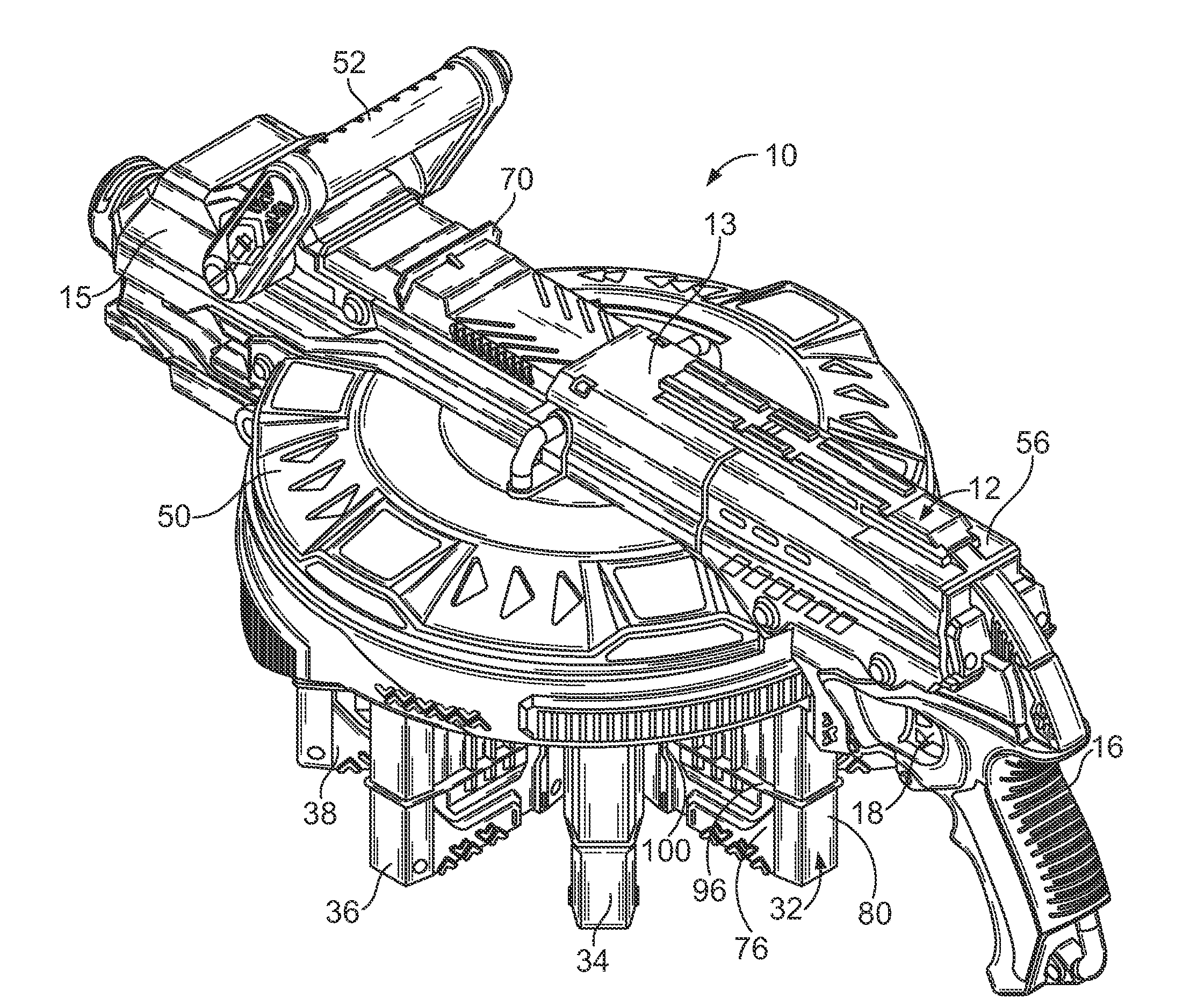
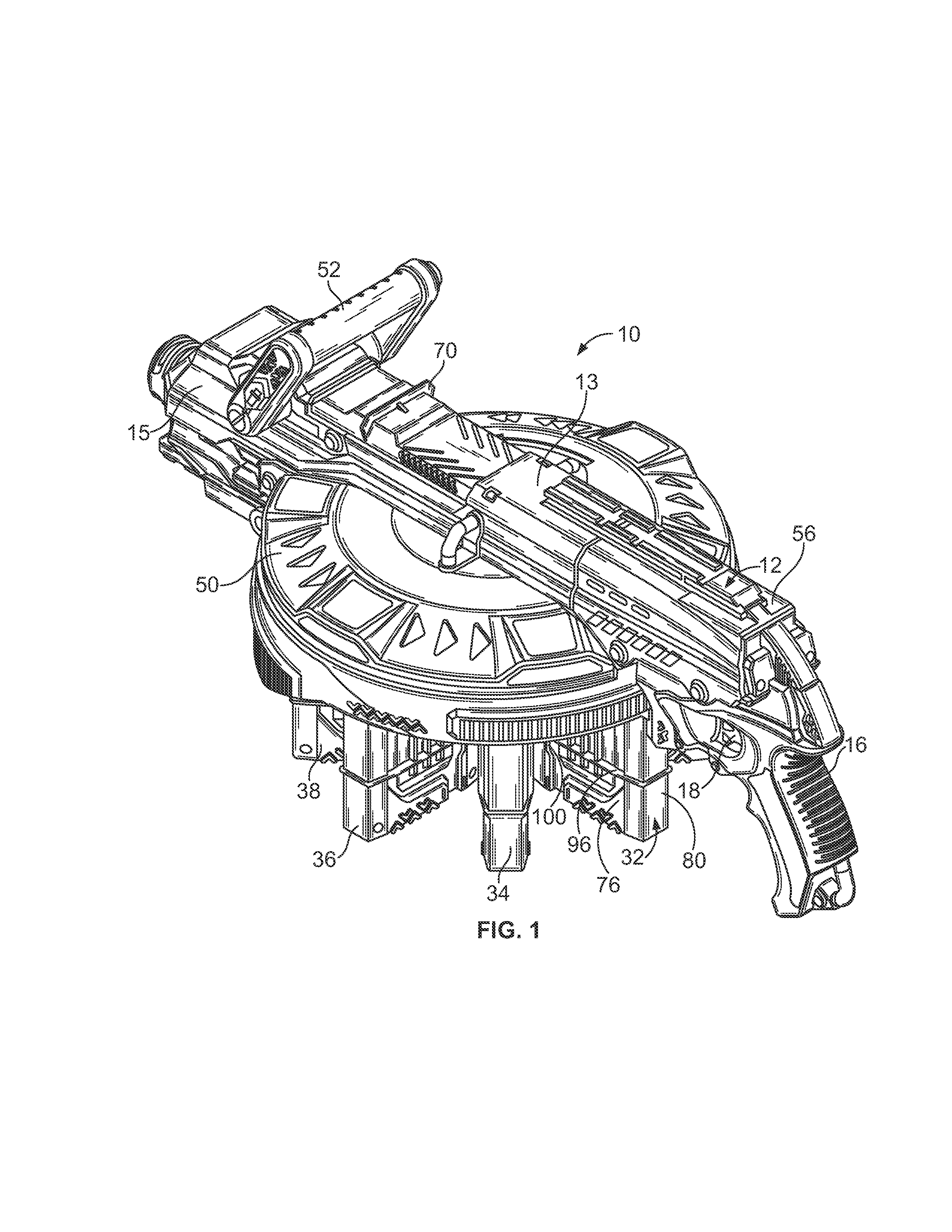
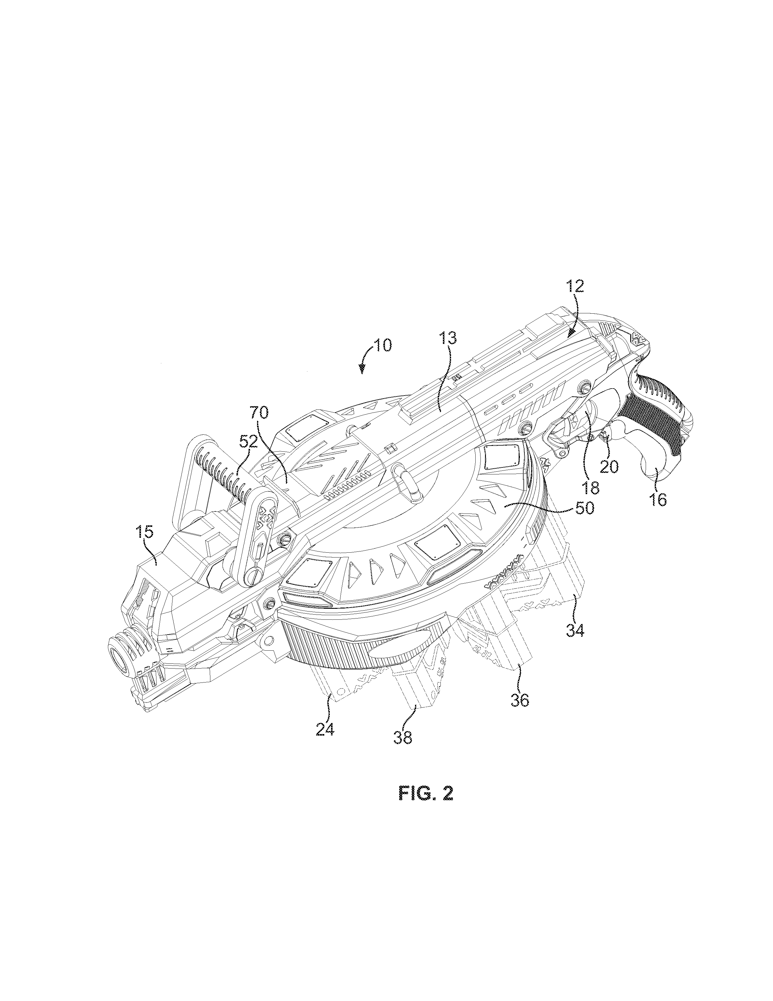
[0024]Referring now to FIGS. 1-3, a toy projectile launcher, gun or blaster 10 is illustrated having a housing 12 including an upper portion 13, a lower portion 14, a barrel portion 15 and a grip portion 16. A trigger 18 is mounted to the grip portion 16, as is a power switch 20, located below the trigger. Extending downward from the lower portion 14 of the housing is a rotatable clip holder or connector 22 to which may be mounted eight projectile clips 24, 26, 28, 30, 32, 34, 36, 38. Each projectile clip contains a plurality of projectiles in ...


PUM

PropertyMeasurementUnit
rotationaaaaaaaaaa
weightaaaaaaaaaa
radiiaaaaaaaaaa

Abstract

A toy launcher apparatus with a rotatable clip connector mounted to a lower portion of a housing. The housing also includes an upper portion, a barrel portion and a grip portion. Pivotally mounted to the upper portion of the housing is a handle and mounted to the grip portion is a trigger and a switch. Attached to the clip connector may be eight projectile clips and the clip connector is rotatable 45° every time the handle is pivoted forward. Mounted within the housing are a battery compartment, and a wheel and motor assembly. Batteries in the battery compartment may power the wheel and motor assembly after the switch is activated by a user. Pulling the trigger causes a projectile, such as a foam dart, to be pushed from a clip aligned with the barrel portion toward spinning wheels of the wheel and motor assembly, and the wheels cause discharge the dart.

Description

FIELD OF THE INVENTION[0001]The present invention relates generally to a toy projectile launcher, and, more particularly, to a toy projectile launcher with a rotatable clip connector where each clip is capable of holding multiple projectiles thereby giving the launcher great projectile capacity.BACKGROUND OF THE INVENTION[0002]Cartridge and projectile feeders or magazines for real and toy guns have long been known and are disclosed in a number of earlier patents. By way of example, U.S. Pat. No. 7,188 for “Feeders For Repeating Fire-Arms” issued in 1876 to Broadwell and purports to disclose a cartridge filled rotatable cylinder for placement atop a multi-barrel Gatling gun. Cartridges are arranged radially in stacked columns. When a stack is positioned above a delivery opening, the cartridges drop to a lip structure and into a barrel. The lip structure prevents premature entry of a cartridge into a barrel. At the top of each stack are a movable weight and a spring. U.S. Pat. No. 2,3...

Claims


Application Information

Patent Timeline
Patent Type & Authority Applications(United States)
IPC IPC(8): F41B4/00F41A9/68
CPCF41A9/68F41A9/26F41A9/63F41A9/73F41A9/74F41B4/00Y10T29/49826
Inventor MEAD, RAYMOND AARONJABLONSKI, BRIAN C.FLAKOWSKI, II, JOHN MICHAEL
Owner HASBRO INC
Why Eureka
Try Eureka