Supercharge Your Innovation With Domain-Expert AI Agents!

Phase Plate for a TEM

a phase plate and electron microscope technology, applied in the direction of material analysis using wave/particle radiation, instruments, nuclear engineering, etc., can solve the problem of low visibility of large objects/structures

Active Publication Date: 2013-11-28
FEI CO
View PDF7 Cites 10 Cited by
  • Summary
  • Abstract
  • Description
  • Claims
  • Application Information

AI Technical Summary

Benefits of technology

The patent describes an improved phase plate that allows for the tuning of the CTF (which controls the focusing of light) for different spatial frequencies with different phase shifts. This is achieved by using a first thin film to cause a second phase shift, and a second thin film to cause a different phase shift. This results in a more precise and accurate tuning of the CTF.

Problems solved by technology

A problem arises in that the Contrast Transfer Function (CTF) for low spatial frequencies in the image is zero or close to zero, resulting in low visibility of large objects / structures.

Method used


Image

  • Phase Plate for a TEM
  • Phase Plate for a TEM
  • Phase Plate for a TEM

Examples


first embodiment

[0057]FIG. 3a schematically shows a phase plate according to the invention.

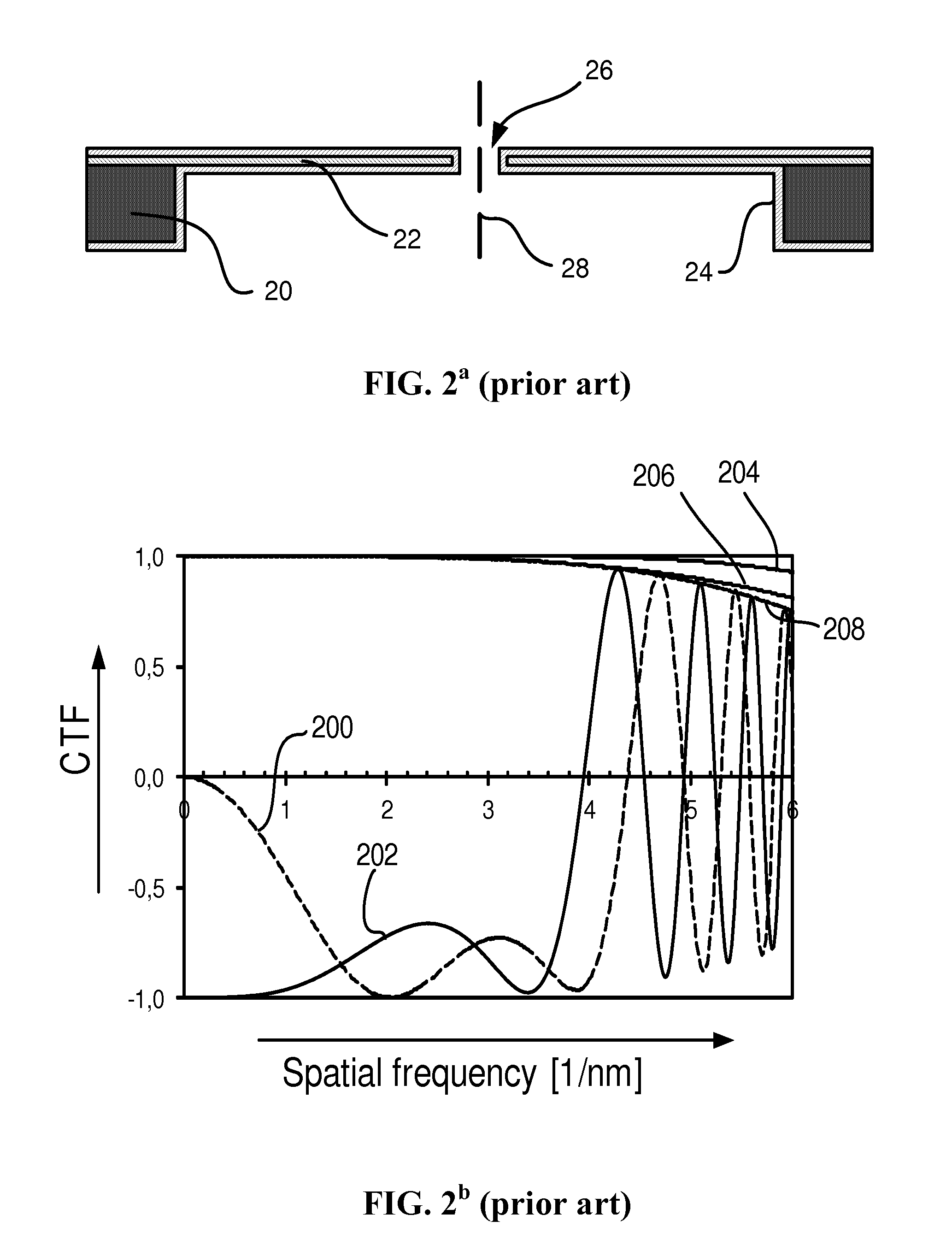
[0058]The phase plate shows a similar holder structure 20 as the prior art phase plate. A thin film 30 is mounted on the holder, the thin layer having little effect on the beam. Inside diameter D1 an extra layer 32 is added to the thin layer, thus forming a first thin film with added thickness, whereby the part of the phase plate inside D1 resembles the prior art phase plate, showing a thin film that causes a phase shift of −π / 2, but between D1 and the inner perimeter of the holder the film is much thinner and the phase shift much smaller than in prior art phase plates. The result is that electrons passing through the film 32 are shifted over −π / 2, but electrons passing though the phase plate outside D1 are shifted much less, for example over −π / 10 (for 300 keV corresponding to a carbon layer of approximately 6 nm). Therefore the CTF for these electrons resembles the CTF of a conventional microscope without p...

third embodiment

[0068]FIG. 5 shows the phase plate according to the invention. In this embodiment the scattering of the further thin film is further diminished by forming the film as a number of spokes 50. The first thin film is now only partly surrounded by the further thin film, but most of the first thin film is surrounded by empty spaces 52. Electrons passing through these empty spaces are not scattered, and only part of the electrons impinging on the spokes are scattered. The phase difference of the electrons passing through the empty space and the spokes is small, and therefore the CTF of electrons falling on the spokes and those passing between the spokes is minimal. Therefore the image reconstructed by the interference of electrons in the image plane (at the detector or fluorescent screen) will be isotropic: it does not or hardly show an angular dependency in CTF caused by the phase plate.

[0069]It is noted that the scattering of electrons by the thin film does not lead to a different CTF, b...


PUM


Abstract

A phase plate, specifically a Zernike type phase plate, for use in an electron microscope, comprises a central hole, and a thin film causing a phase shift of the electrons passing through said film. This phase shift causes the Contrast Transfer Function (CTF) to change from a sine-like function to a cosine-like function.The phase plate is equipped with a film in the form of an annulus, carried by a much thinner film. As a result only in a small spatial frequency range (for low frequencies) the phase is changed (and thus the CTF), and for other spatial frequencies the phase shift is negligible, and thus the CTF remains unchanged. Due to the much smaller thickness of the carrier film the scattering of electrons is negligible as well.

Description

[0001]This Application claims priority from U.S. Provisional Application 61 / 650,584, filed May 23, 2012, which is hereby incorporated by reference.TECHNICAL FIELD OF INVENTION [0002]The invention relates to a phase plate for an electron microscope, the microscope generating a beam of electrons, said beam of electrons passing through a sample, the beam of electrons after passing through the sample divided in an undiffracted beam and a diffracted beam, the sample imaged in an image plane where the undiffracted and the diffracted beams interfere to form an image, the phase plate placed in a plane where the undiffracted and the diffracted beam are focused, the phase plate comprising:[0003]A central area, said central area in working causing a first phase shift,[0004]A first thin film surrounding and bordering the central area, said first thin film in working causing a second phase shift differing from the first phase shift,[0005]A holder structure surrounding the first thin film for hol...

Claims


Application Information

Patent Timeline
Patent Type & Authority Applications(United States)
IPC IPC(8): H01J37/26
CPCH01J37/263H01J2237/2614H01J2237/2802
Inventor BUIJSSE, BART
Owner FEI CO
Features
  • R&D
  • Intellectual Property
  • Life Sciences
  • Materials
  • Tech Scout
  • Unparalleled Data Quality
  • Higher Quality Content
  • 60% Fewer Hallucinations
Learn More