Memory systems and methods for controlling the timing of receiving read data

a memory device and read data technology, applied in memory systems, climate sustainability, instruments, etc., can solve the problems of increasing the operating speed of memory devices, requiring a certain amount of time to service, and the increase in the speed of devices cannot keep up with the increase in the operating speed of processors

Active Publication Date: 2013-11-28
MICRON TECH INC
View PDF0 Cites 14 Cited by
  • Summary
  • Abstract
  • Description
  • Claims
  • Application Information

AI Technical Summary

Benefits of technology

The patent text describes a system and method for controlling memory devices in a computer system. The system includes a memory controller that controls multiple memory devices. The memory controller uses a common interface to communicate with the memory devices. However, there is a risk of data collisions on the interface if multiple memory devices are controlled by the same memory controller. To address this problem, the patent proposes a system that avoids data collisions without relying on a common clock signal at the memory device. This reduces complexity and space consumption, and improves overall memory access bandwidth.

Problems solved by technology

Memory devices require a certain amount of time to service a memory request due to the time necessary to access the appropriate rows and columns of the memory device and actually retrieve the requested data.
Although the operating speed of memory devices is continually increasing, the increase in device speed has not kept pace with increases in the operating speed of processors.
The operation of the memory device itself therefore often limits the bandwidth of communication between the processor and the system memory.
When a memory controller shares a common interface with multiple memory devices however, timing problems may occur.
Furthermore, different memory devices may take different amounts of time to respond to memory commands depending on the process variations that occurred during fabrication of the memory devices.
Variations in temperature may also cause variation in response time between memory devices.
Accordingly, there is a danger of a conflict on the common interface between multiple memory devices and a memory controller.
Such a data collision would result in a loss of usable data and is unacceptable.
However, the transmission of clock signals for each memory device may increase complexity of the system and consumes space and power at the memory device.

Method used


Image

  • Memory systems and methods for controlling the timing of receiving read data
  • Memory systems and methods for controlling the timing of receiving read data
  • Memory systems and methods for controlling the timing of receiving read data

Examples


Embodiment Construction

[0014]Embodiments of the present invention are directed toward memory systems and methods for controlling memory devices. Certain details are set forth below to provide a sufficient understanding of embodiments of the invention. However, it will be clear to one skilled in the art that embodiments of the invention may be practiced without various of these particular details. In some instances, well-known circuits, control signals, timing protocols, and software operations have not been shown in detail in order to avoid unnecessarily obscuring the described embodiments of the invention.

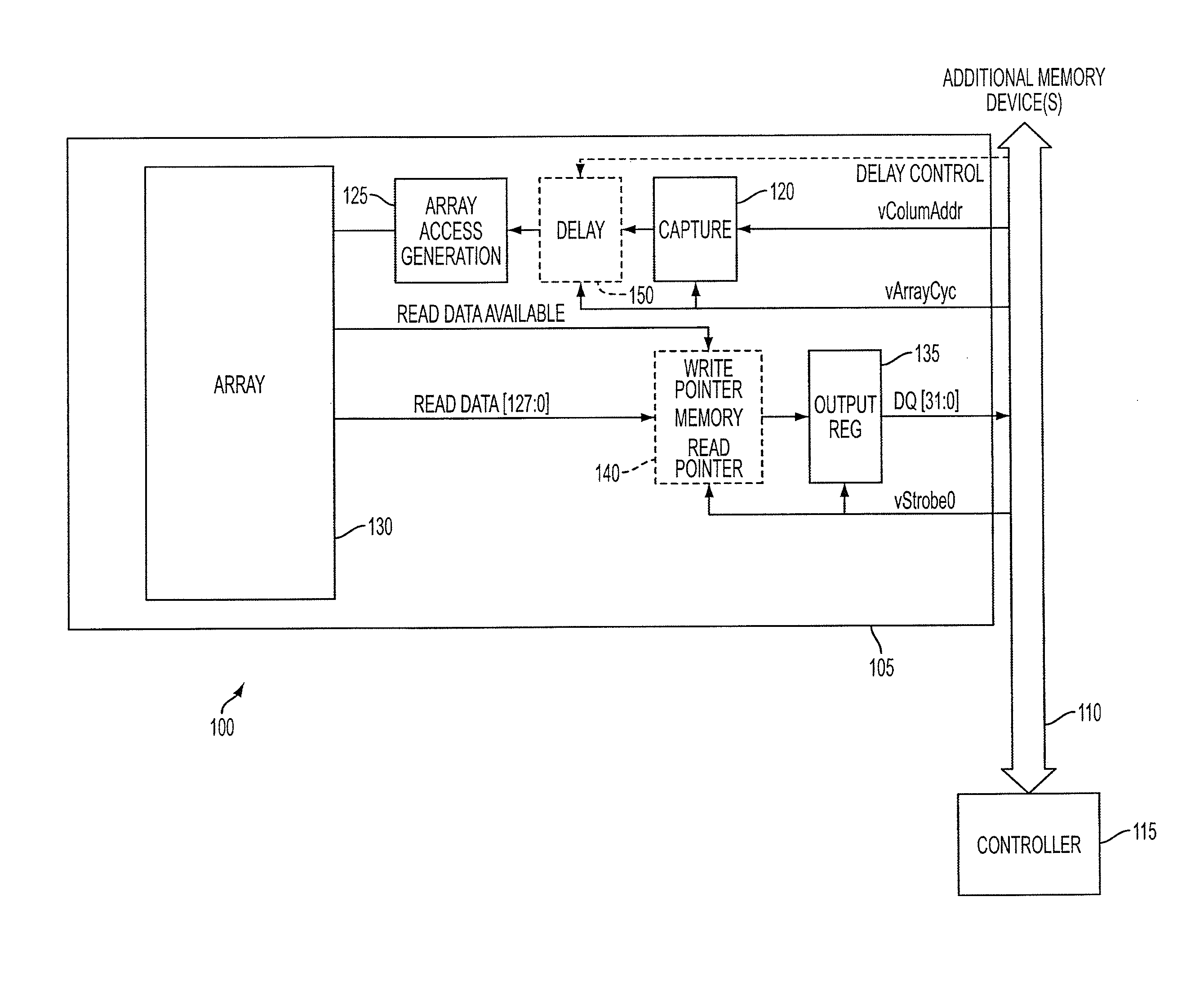
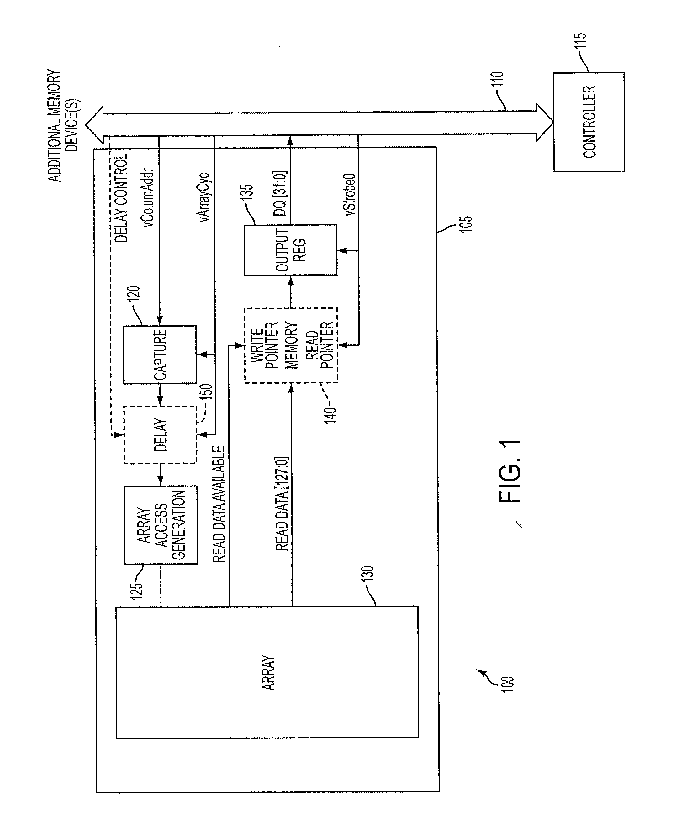
[0015]A system 100 according to an embodiment of the present invention is shown in FIG. 1. The system 100 includes a plurality of memory devices, including memory device 105. The memory device 105 and other memory devices (not shown) share an interface 110 with a controller 115. The interface 110 may be implemented, for example, as a bus including a high-speed bus. In some embodiments, the memory device...


PUM


Abstract

Embodiments of the present invention provide memory systems having a plurality of memory devices sharing an interface for the transmission of read data. A controller can identify consecutive read requests sent to different memory devices. To avoid data contention on the interface, for example, the controller can be configured to delay the time until read data corresponding to the second read request is placed on the interface.

Description

CROSS REFERENCE TO RELATED APPLICATION(S)[0001]This application is a continuation of pending U.S. patent application Ser. No. 12 / 128,883, filed May 29, 2008, which application is incorporated herein by reference, in its entirety, for any purpose.TECHNICAL FIELD[0002]Embodiments of the invention relate to memory systems and methods for controlling memory devices.BACKGROUND OF THE INVENTION[0003]Processor-based systems use memory devices, such as dynamic random access memory (“DRAM”) devices, to store data (e.g. representing instructions, data to be processed, etc.) that are accessed by the processor. In a typical computer system, the processor communicates with the system memory including the memory devices through a processor bus and one or more memory controllers. In some memory systems, a group of memory devices of the system memory are controlled by an associated memory controller. The processor issues to the memory controller a memory request including a memory command, such as ...

Claims


Application Information

Patent Timeline
Patent Type & Authority Applications(United States)
IPC IPC(8): G06F3/06
CPCG06F3/0611G06F3/0689G06F3/0629G06F13/1689Y02D10/00G06F5/06G11C7/1051G11C7/222G06F3/0683G06F3/0604G06F3/0659G06F3/0673
Inventor LABERGE, PAUL A.JOHNSON, JAMES B.
Owner MICRON TECH INC
Why Eureka
Try Eureka