Method and system for providing direct data placement support

a technology for direct data and placement support, applied in the field of direct data placement, can solve the problems of increasing the effective cost of a toe implementation, and further restricting the approach, so as to reduce the overhead of cpu processing, reduce the requirement of buffer storage space, and reduce the overhead of data copying

Inactive Publication Date: 2006-02-16
IBM CORP
View PDF10 Cites 53 Cited by
  • Summary
  • Abstract
  • Description
  • Claims
  • Application Information

AI Technical Summary

Benefits of technology

[0010] Disclosed is a system and method supporting direct data placement in a network adapter and providing for the reduction of CPU processing overhead associated with direct data transfer. In an initial phase, parameters relevant to direct data placement are extracted by hardware logic implemented in a network adapter during processing of packet headers and are stored in a control structure instantiation. Payload data subsequently received at a network adapte...

Problems solved by technology

As data transmission speeds over Ethernet increase from a single gigabit per second (Gbps) to tens of Gbps and beyond, a host central processing unit (CPU) becomes less and less capable of processing packets that are received and transmitted at these high data rates.
However, a TOE approach is limited in its need for a large, dedicated reassembly buffer to handle out-of-order TCP packets, thereby increasing the effective cost of a TOE implementation.
The TOE approach is further limited by the cost and complexity associated with implementing a TCP/IP protocol stack in a network adapter, potentially increasing its time-to-market.
A TCP/IP stack as implemented in a programmable TOE is potentially more difficult to update than a stack implementation in a host operating system (OS) and has the potential to be even more difficult ...

Method used


Image

  • Method and system for providing direct data placement support
  • Method and system for providing direct data placement support
  • Method and system for providing direct data placement support

Examples


Embodiment Construction

[0018] While this invention is illustrated and described in a preferred embodiment, the invention may be produced in many different configurations. There is depicted in the drawings, and will herein be described in detail, a preferred embodiment of the invention, with the understanding that the present disclosure is to be considered as an exemplification of the principles of the invention and the associated functional specifications for its construction and is not intended to limit the invention to the embodiment illustrated. Those skilled in the art will envision many other possible variations within the scope of the present invention.

I. Hardware Support of Accelerating Packet Reception and Transmission

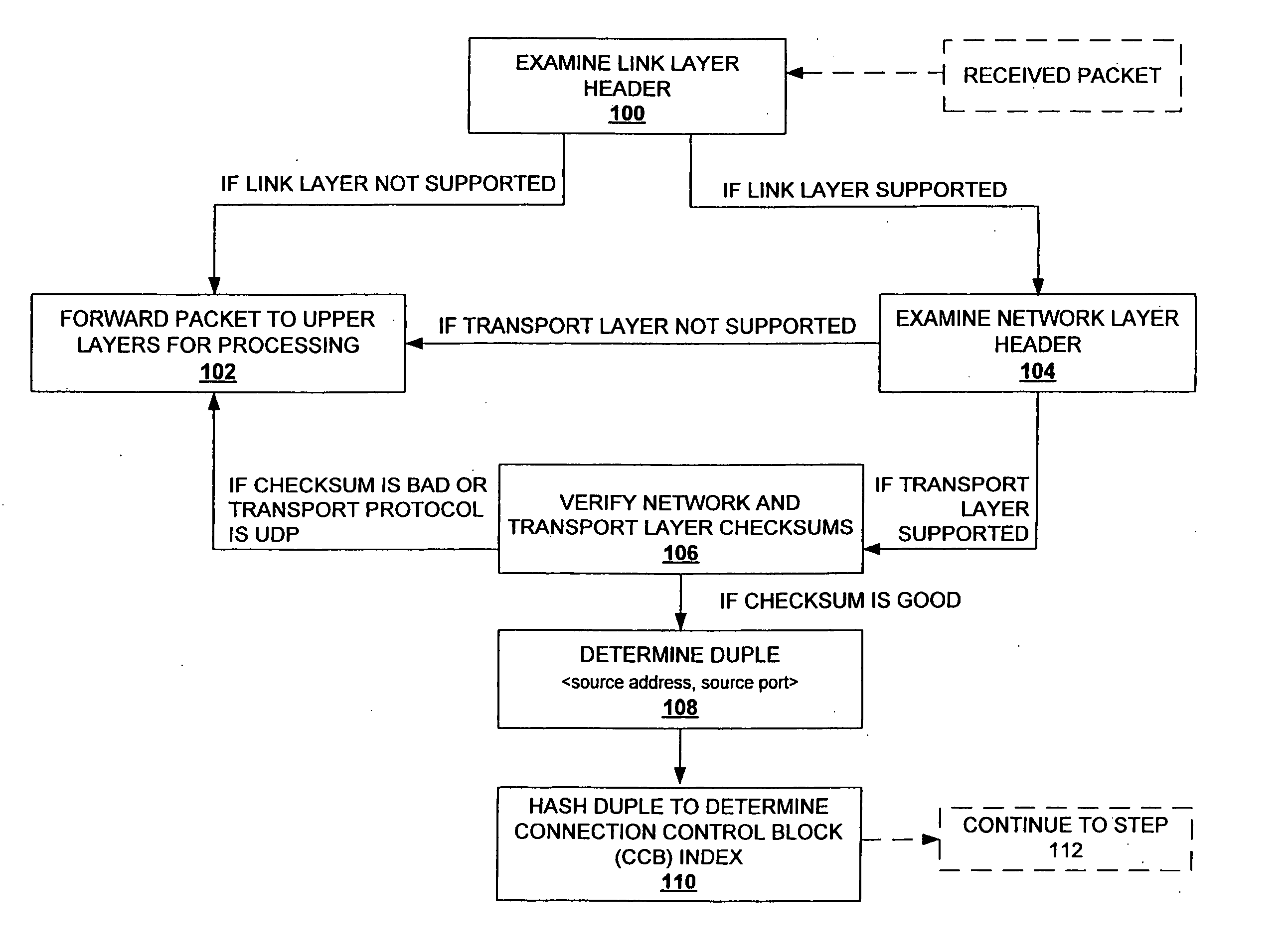
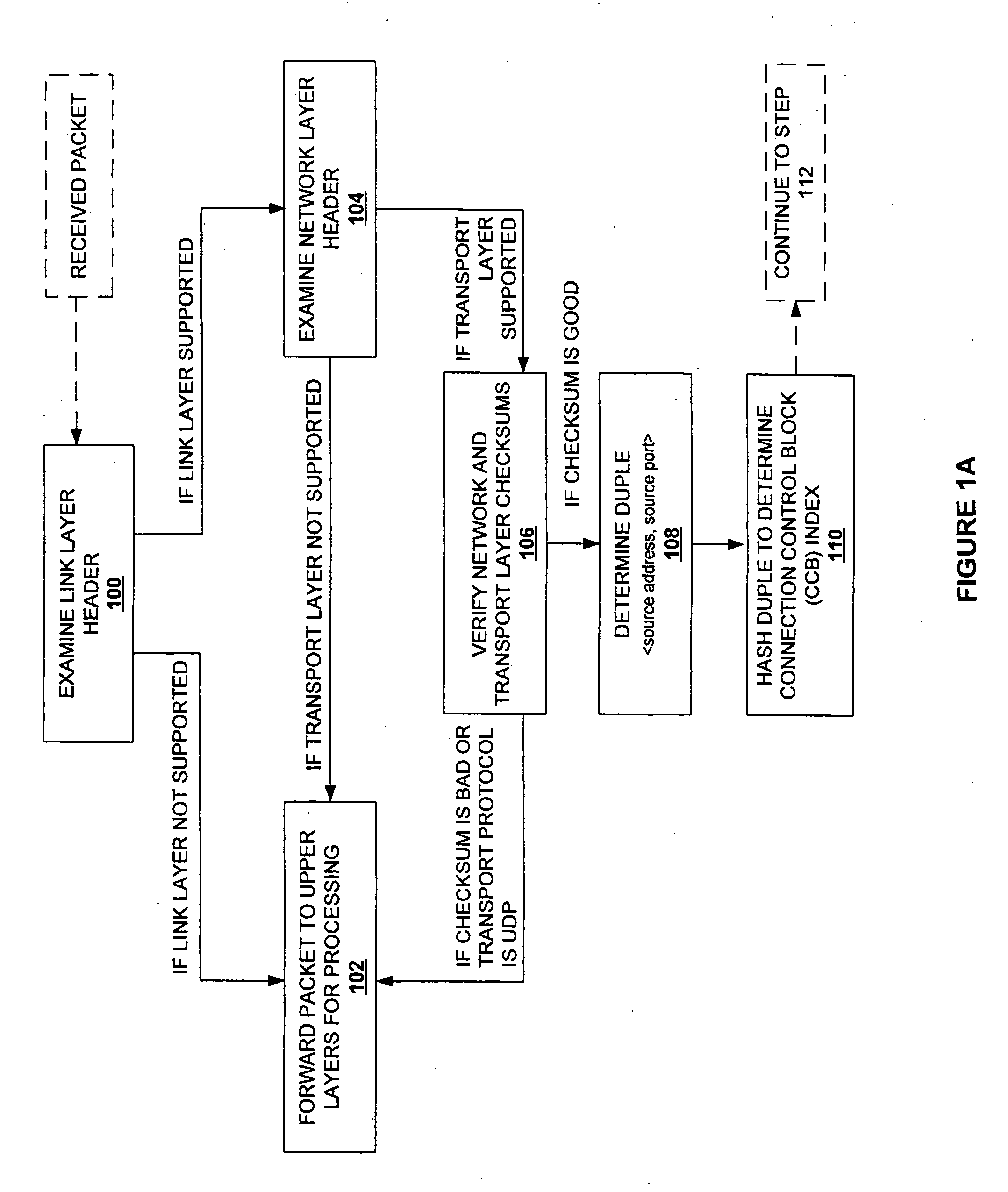
[0019] Referring now to FIG. 1a, a process flow diagram for the first phase of processing a packet received over a network connection, is shown. Upon receipt of a packet, it is determined whether the received packet meets eligibility requirements for hardware acceleration support ...


PUM


Abstract

A system and method for reducing the overhead associated with direct data placement is provided. Processing time overhead is reduced by implementing packet-processing logic in hardware. Storage space overhead is reduced by combining results of hardware-based packet-processing logic with ULP software support; parameters relevant to direct data placement are extracted during packet-processing and provided to a control structure instantiation. Subsequently, payload data received at a network adapter is directly placed in memory in accordance with parameters previously stored in a control structure. Additionally, packet-processing in hardware reduces interrupt overhead by issuing system interrupts in conjunction with packet boundaries. In this manner, wire-speed direct data placement is approached, zero copy is achieved, and per byte overhead is reduced with respect to the amount of data transferred over an individual network connection. Movement of ULP data between application-layer program memories is thereby accelerated without a fully offloaded TCP protocol stack implementation.

Description

BACKGROUND OF THE INVENTION [0001] 1. Field of Invention [0002] The present invention relates generally to the field of direct data placement. More specifically, the present invention is related to reliable, direct data placement supported by transport layer functionality implemented in both software and hardware. [0003] 2. Discussion of Prior Art [0004] As data transmission speeds over Ethernet increase from a single gigabit per second (Gbps) to tens of Gbps and beyond, a host central processing unit (CPU) becomes less and less capable of processing packets that are received and transmitted at these high data rates. One approach to meeting demands associated with increased data transmission speeds is to offload onto hardware, computation-intensive upper layer packet processing functionality that is traditionally implemented in software. Usually transferred to hardware in the form of a network adapter, also known as a network interface card (NIC), such an offload reduces packet proc...

Claims


Application Information

Patent Timeline
IPC IPC(8): H04L12/56
CPCH04L63/12H04L69/161H04L69/16
Inventor KO, MICHAEL ANTHONYRECIO, RENATO J.SARKAR, PRASENJIT
Owner IBM CORP
Why Eureka
Try Eureka