Exhaust gas recirculation apparatus for engine

a technology of exhaust gas and egr, which is applied in mechanical equipment, machines/engines, electric control, etc., can solve the problems of egr control failure, step-out of step motor, and foreign matter lodged or caught between the valve seat and the valve element, etc., and achieve the effect of reliable removal of foreign matter

Active Publication Date: 2013-12-05
AISAN IND CO LTD
View PDF3 Cites 12 Cited by
  • Summary
  • Abstract
  • Description
  • Claims
  • Application Information

AI Technical Summary

Benefits of technology

[0014]According to the invention, it is possible to reliably remove foreign matters which are stuck to a valve seat or a valve element in an EGR valve or lodged between the valve seat and the valve element.

Problems solved by technology

In this type of EGR valve, a problem may occur in which foreign particles such as carbon particles in exhaust gas or hard foreign matters such as cutting chips are lodged or caught between the valve seat and the valve element.
This may cause step-out of the step motor and hence failures of EGR control.

Method used


Image

  • Exhaust gas recirculation apparatus for engine
  • Exhaust gas recirculation apparatus for engine
  • Exhaust gas recirculation apparatus for engine

Examples


first embodiment

[0028]A detailed description of a preferred first embodiment of an exhaust gas recirculation apparatus for engine embodying the present invention will now be given referring to the accompanying drawings.

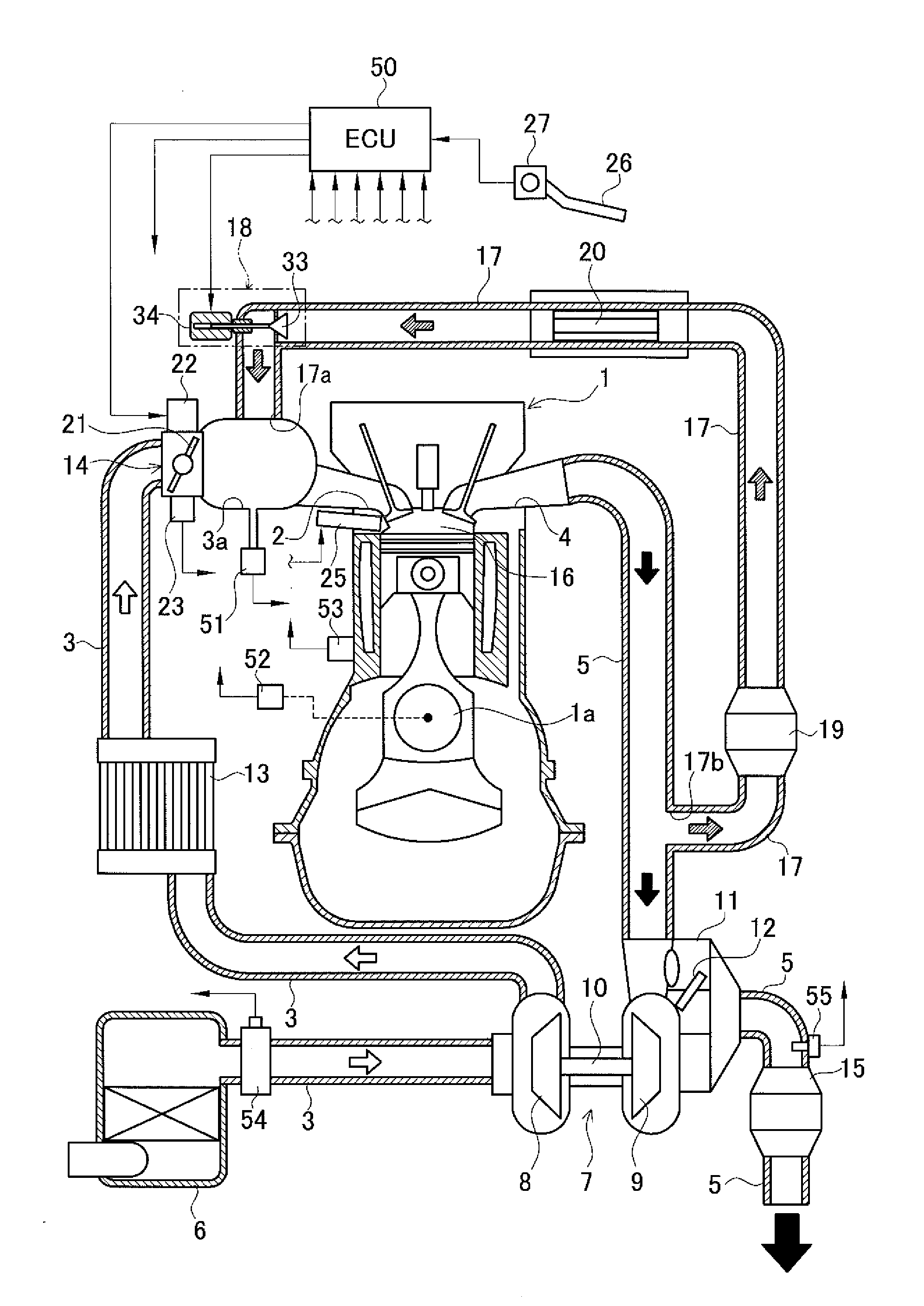
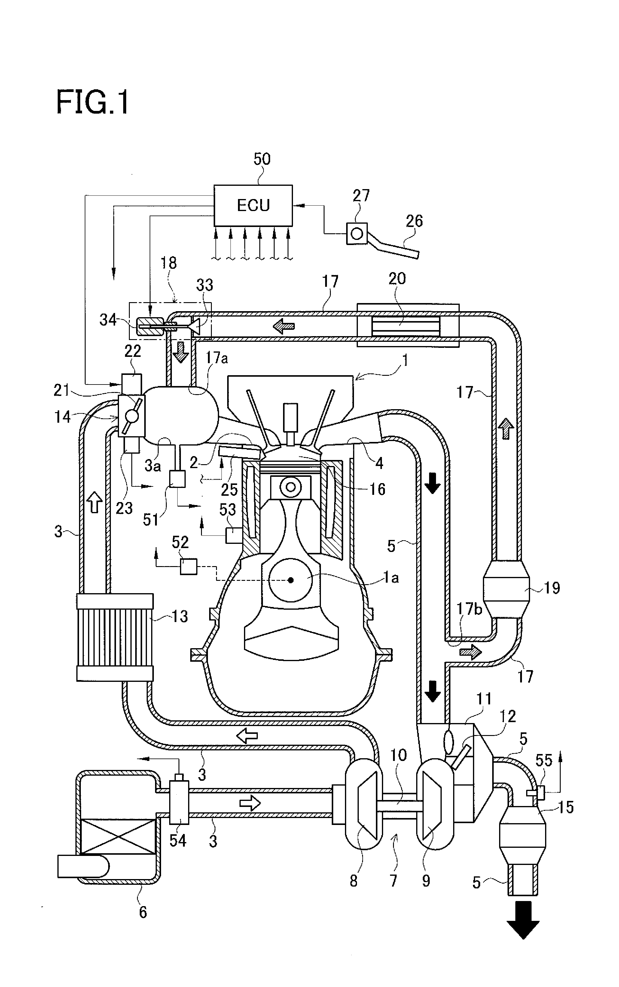
[0029]FIG. 1 is a schematic configuration view of a supercharger-equipped engine system including an exhaust gas recirculation (EGR) apparatus for engine in this embodiment. This engine system includes a reciprocating-type engine 1. This engine 1 has an intake port 2 connected to an intake passage 3 and an exhaust port 4 connected to an exhaust passage 5. An air cleaner 6 is provided at an inlet of the intake passage 3. In the intake passage 3 downstream from the air cleaner 6, a supercharger 7 is placed in a position between a portion of the intake passage 3 and a portion of the exhaust passage 5 to raise the pressure of intake air in the intake passage 3.

[0030]The supercharger 7 includes a compressor 8 placed in the intake passage 3, a turbine 9 placed in the exhaust passage 5, and...

second embodiment

[0120]A second embodiment of an exhaust gas recirculation apparatus for engine according to the invention will be described in detail below referring to the accompanying drawing.

[0121]In the following explanation, similar or identical parts to those in the first embodiment are given the same reference signs as those in the first embodiment. The following explanation is thus focused on differences from the first embodiment.

[0122]The present embodiment differs from the first embodiment in the details of the foreign-matter lodging prevention processing. FIG. 12 is a flowchart showing one example of the details of the foreign-matter lodging prevention control processing to be executed by the ECU 50.

[0123]The flowchart shown in FIG. 12 differs from the flowchart shown in FIG. 11 in the details of processings in Steps 455 and 500. The Step 455 in the flowchart in FIG. 12 corresponds to the Step 450 in the flowchart in FIG. 11. The details of processings in other Steps 400 to 440 and 460 t...

third embodiment

[0127]A third embodiment embodying an exhaust gas recirculation apparatus for engine according to the present invention will be explained in detail below referring to the accompanying drawing.

[0128]FIG. 13 is a schematic configuration view showing a supercharger-equipped engine system including an EGR apparatus in this embodiment. The present embodiment differs from the first and second embodiments in placement of the EGR apparatus as shown in FIG. 13. In the present embodiment, specifically, the EGR passage 17 is connected, at its inlet 17b, to the exhaust passage 5 downstream of the catalytic convertor 15 and, at its outlet 17a, to the intake passage 3 upstream of the compressor 8 of the supercharger 7. Other configurations are identical to those in each of the above embodiments.

[0129]According to the present embodiment, while the engine 1 is operating and also the EGR valve 18 is being open during operation of the supercharger 7, the negative pressure resulting from the superchar...


PUM


Abstract

An EGR apparatus includes a EGR passage for allowing part of exhaust gas discharged from a combustion chamber of an engine to an exhaust passage to flow in an intake passage and recirculate back to the combustion chamber, and an EGR valve provided in the EGR passage to regulate an EGR passage in this passage. The EGR valve includes a valve seat, a valve element to be seatable on the valve seat, and a step motor for driving the valve element to open and close. An electronic control device controls the EGR valve to repeat opening and closing of the valve element between a closing position and a small opening position in order to remove foreign matters adhered to the valve seat or valve element during deceleration fuel cutoff of the engine.

Description

CROSS-REFERENCE TO RELATED APPLICATIONS[0001]This application is based upon and claims the benefit of priority from the prior Japanese Patent Application No. 2012-125044, filed May 31, 2012, the entire contents of which are incorporated herein by reference.BACKGROUND OF THE INVENTION[0002]1. Field of the Invention[0003]The present invention relates to an exhaust gas recirculation (EGR) apparatus for engine to allow part of exhaust gas discharged from an engine to an exhaust passage to flow in an intake passage to recirculate back to the engine.[0004]2. Related Art[0005]Conventionally, a technique of the above type is employed in a vehicle engine. An exhaust gas recirculation (EGR) apparatus is arranged to introduce part of exhaust gas after combustion, which is discharged from a combustion chamber of an engine to an exhaust passage, into an intake passage through an EGR passage so that the exhaust gas is mixed with intake air flowing in the intake passage and flows back to the combu...

Claims


Application Information

Patent Timeline
Patent Type & Authority Applications(United States)
IPC IPC(8): F02M25/07
CPCF02M25/0701F02D41/0077F02D41/123F02D41/005F02D2200/0406F02M26/05F02M26/06F02M26/50F02M26/22F02M26/35F02M26/53Y02T10/40
Inventor YOSHIOKA, MAMORU
Owner AISAN IND CO LTD
Why Eureka
Try Eureka