Air gun firing operating system

a firing system and air gun technology, applied in the field of air gun firing system, can solve the problems of circuit board being sold without warranty of parts, malfunction of the system, and failure of the movement of the suppressed valve pin, so as to avoid the risk of bullets traveling too fast during firing and endanger the environment or the gun structur

Active Publication Date: 2013-12-05
CHO CHAO HSIUNG +3
View PDF7 Cites 11 Cited by
  • Summary
  • Abstract
  • Description
  • Claims
  • Application Information

AI Technical Summary

Benefits of technology

[0014]A fourth objective of the present invention lies in the cylinder connected to an air pressure regulating system, in which the air pressure regulating system is installed with a pressure regulating device and an overpressure protection device and a flo...

Problems solved by technology

However, this solenoid valve is frequently subjected to change in pressure value of the pressure source, causing a change in the working condition and resulting in malfunction of the system.
Furthermore, if the value of the force components is greater than the electromagnetic force, then movement of the suppressed valve pin is caused to fail.
However, it is common for the circuit board to be often sold without warranty of parts.
The reason for which is very simple, because the circuit board is unable to withstand mechanical vibration forces, and high-speed firing effects high-frequency movement which very easily damages the circuit board.
Hence, such a design is really not appropriate for use in high vibrating guns.
Moreover, the circuit needs a power supply to operate, and it is common for a user to forget to turn off the power supply after finishing their game activities, thereby causing the power supply to completely drain after the gun has been put away for about 3 to 5 days (varying depending on power consumption).
Related electronic control problems are really not suitable for actual needs, and many designs have abandoned the continuous firing operation, instead adopting a design whereby the finger is used to effect a pulling action on the trigger to effect a single shot operation, such as Gabrel's U.S. Pat. No. 8,033,276.
Moreover, the high-pressure device is disposed to match the storage chamber, thus, the design of the accumula...

Method used


Image

  • Air gun firing operating system
  • Air gun firing operating system
  • Air gun firing operating system

Examples


Embodiment Construction

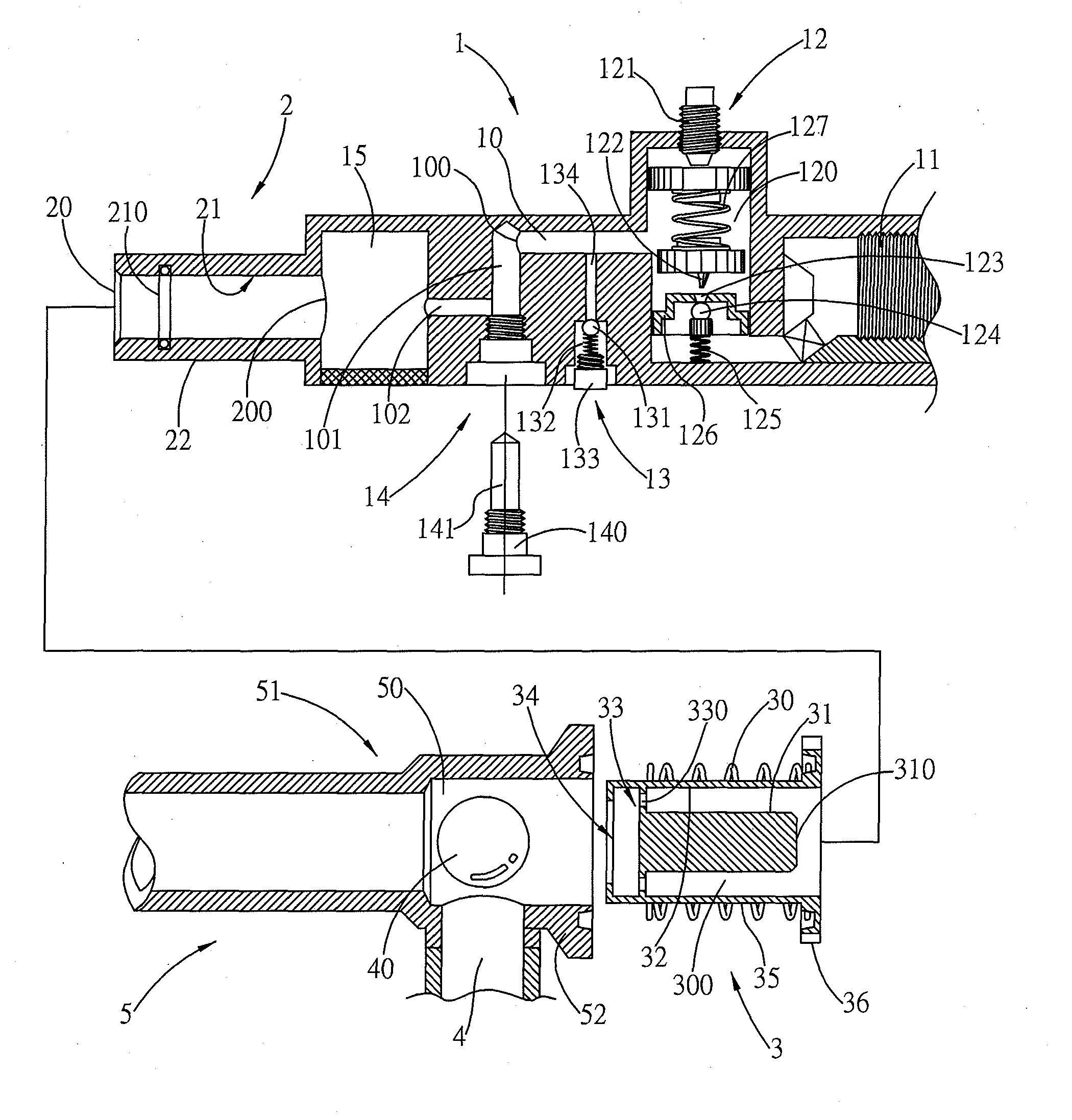
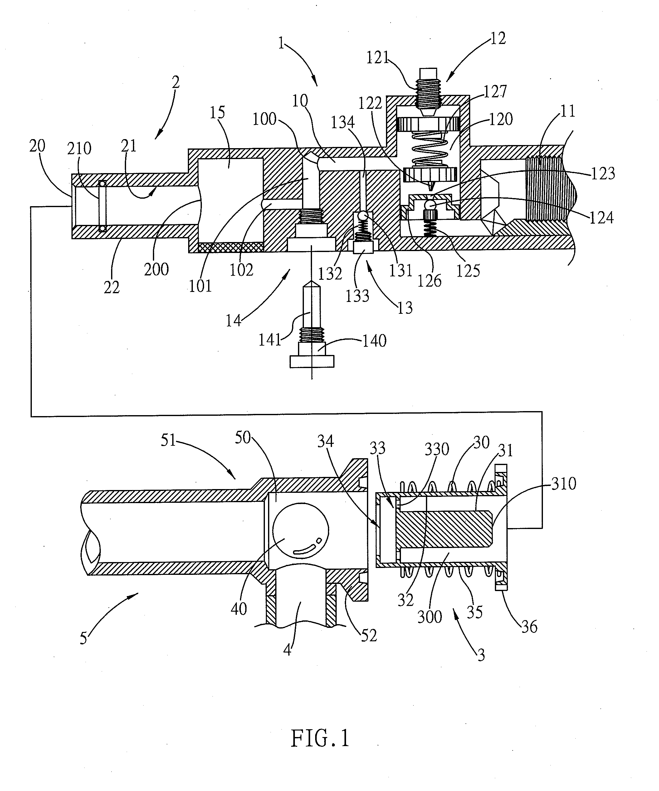
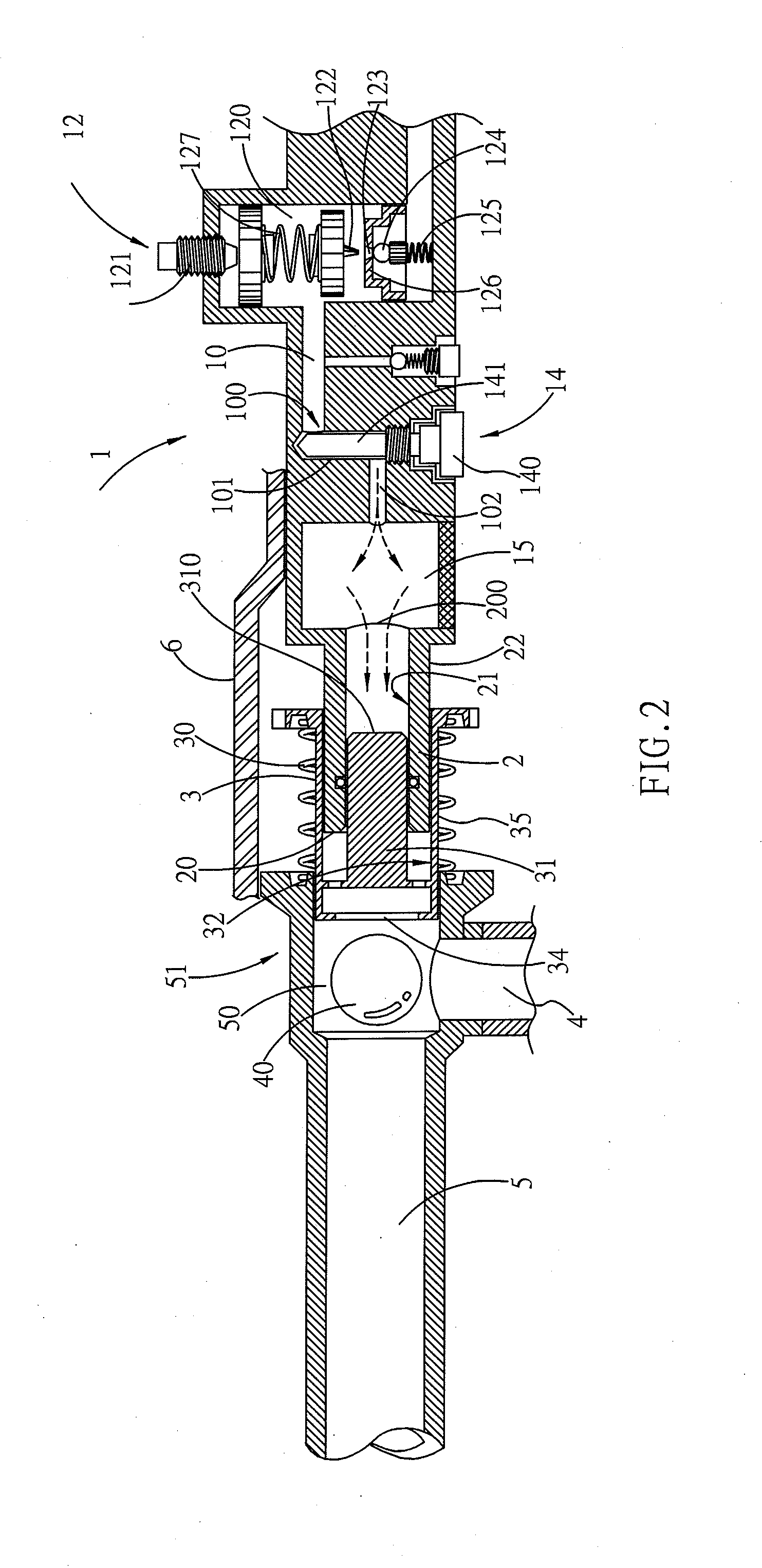
[0023]Referring first to FIG. 1, the present invention primarily comprises a sleeve-shaped sliding shuttle tube 3. The interior of the sliding shuttle tube 3 is fitted with a sliding column 31, and the sliding column 31 is disposed to slide on a cylinder body 21 fitted in the center of a cylinder 2. A shuttling outer circumferential surface 35 of the sliding shuttle tube 3 is disposed to slide in the inner circumference of a cylinder-shaped bullet chamber 50 that is connected and fixed to a gun barrel 5. A sliding inner circumferential surface 32 of the sliding shuttle tube 3 is further slidably mounted on a cylindrical outer circumferential surface 22 of a cylinder 2, causing a movable airtight tolerance to be formed between the sliding column 31 and the cylinder body 21 and between the sliding inner circumferential surface 32 and the cylindrical outer circumferential surface 22. Moreover, such a configuration forms a mutually coaxial (the working shaft of the firing action) socket...


PUM


Abstract

The present invention provides an air gun firing operating system that uses compressed air to eject bullets by purely mechanical means, and enables single firing or high-speed continuous firing. During the firing operation, the system uses a sliding shuttle tube that is able to slide back and forth in a linear displacement on a central axis between a bullet chamber and a cylinder. The sliding shuttle tube uses differential pressure variation in a pressure buffer chamber to achieve a stroke state that can be continuously changed, thereby achieving high-speed back and forth motion and continuous firing of bullets. The relevant driving position of a trigger device is provided with a sliding retainer, which is able to effect transient retaining of the sliding shuttle tube, thereby restricting the system for single firing, or discontinuing the retention to enable the system to be in a continuous firing operation state.

Description

RELATED APPLICATION[0001]This application is a Continuation-In-Part of co-pending U.S. application Ser. No. 13 / 075,738 filed on Mar. 30, 2011, for which priority is claimed under 35 U.S.C. §120; and this application claims priority of Application No. 099146215 filed in Taiwan, R.O.C. on Dec. 28, 2010 under 35 U.S.C. §120; the entire contents of all of which are hereby incorporated by reference.BACKGROUND OF THE INVENTION[0002](a) Field of the Invention[0003]The present invention provides an air gun firing system, which is able to employ a purely mechanical system to achieve a high speed continuous firing or single firing operation. The firing system uses a sliding shuttle tube able to move frontward and rearward between a bullet chamber and a cylinder. The sliding shuttle tube is subjected to a differential pressure variation of a pressure buffer chamber pressure source during the back-and-forth motion thereof, which changes the stroke direction of the sliding shuttle tube, and the ...

Claims


Application Information

Patent Timeline
IPC IPC(8): F41B11/70
CPCF41B11/70F41B11/721F41B11/724F41B11/723F41B11/72
Inventor CHO, CHAO-HSIUNG
Owner CHO CHAO HSIUNG
Why Eureka
Try Eureka