Corrosion/etching protection in integration circuit fabrications

Inactive Publication Date: 2013-12-05
GLOBALFOUNDRIES INC
View PDF5 Cites 21 Cited by
  • Summary
  • Abstract
  • Description
  • Claims
  • Application Information

AI Technical Summary

Benefits of technology

[0006]In a further aspect, an interconnect structure having reduced corrosion includes a first interconnect in a first dielectric, and first insulator portion

Problems solved by technology

In either case, the corrosion/etching of the first interconnect, and the e

Method used


Image

  • Corrosion/etching protection in integration circuit fabrications
  • Corrosion/etching protection in integration circuit fabrications
  • Corrosion/etching protection in integration circuit fabrications

Examples


Embodiment Construction

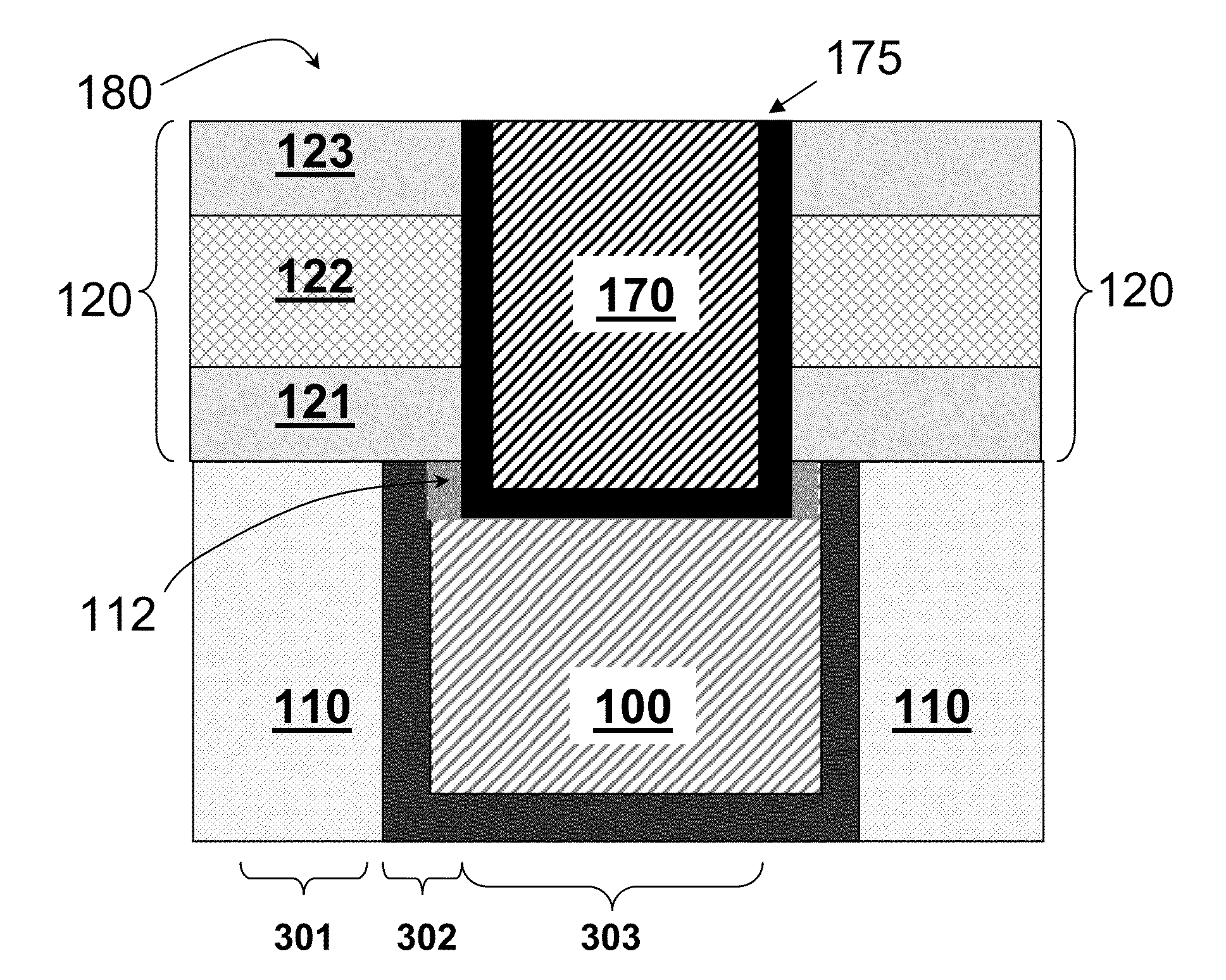
[0026]Embodiments of methods for making a reduced corrosion interconnect structure are described in conjunction with FIGS. 2-8b. An embodiment of interconnect structure with reduced corrosion is described in conjunction with FIGS. 8a-9b. Embodiments in which the first interconnect 110 is not recessed are described in “a” figures and embodiments in which the first interconnect 110 has a recess are described in “b” figures.

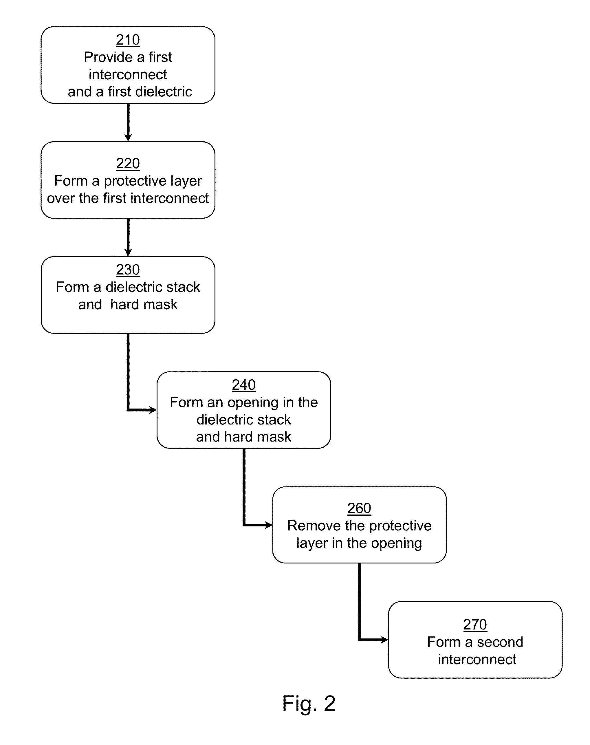
[0027]Referring to FIG. 2, a method for making a reduced corrosion interconnect is shown. The method starts at 210 by providing a first interconnect and a first dielectric which are, preferably, substantially co-planar. In other embodiments, the first interconnect may be recessed with respect to the top surface of the first dielectric. At 220 a protective layer is formed over the first interconnect. In a preferred embodiment, while the protective layer is formed over the first interconnect, a metal silicate layer is simultaneously formed over the first dielectric. I...


PUM


Abstract

A method of producing reduced corrosion interconnect structures and structures thereby formed. A method of producing microelectronic interconnects having reduced corrosion begins with a damascene structure having a first dielectric and a first interconnect. A metal oxide layer is deposited selectively to metal or nonselective over the damascene structure and then thermally treated. The treatment converts the metal oxide over the first dielectric to a metal silicate while the metal oxide over the first interconnect remains as a self-aligned protective layer. When a subsequent dielectric stack is formed and patterned, the protective layer acts as an etch stop, oxidation barrier and ion bombardment protector. The protective layer is then removed from the patterned opening and a second interconnect formed. In a preferred embodiment the metal oxide is a manganese oxide and the metal silicate is a MnSiCOH, the interconnects are substantially copper and the dielectric contains ultra low-k.

Description

FIELD OF THE INVENTION[0001]The present invention generally relates to interconnects of microelectronic devices and method of making the interconnects. In particular, the invention relates to an improved method of forming interconnects to prevent detrimental corrosion or etching of the interconnect by forming a protective layer.BACKGROUND AND RELATED ART[0002]Integrated circuits of microelectronic devices include interconnects to wire together the devices, thus making the circuits. In a typical process for making the interconnects, a first interconnect 100 is embedded in first dielectric material 110 and covered by a stack of dielectric material 120. Above the dielectric stack 120 is a hard mask 130 to aid in forming an opening 140 in the dielectric stack 120 which reaches the first interconnect 100. After the opening 140 is formed, the hard mask 130 is removed with a wet etch which also corrodes / etches 150 a portion of the first interconnect 100. The corrosion / etching 150 of the fi...

Claims


Application Information

Patent Timeline
IPC IPC(8): H01L23/532H01L21/768
CPCH01L23/53238H01L21/76829H01L21/76834H01L21/76888H01L23/5329H01L23/53295H01L2924/0002
Inventor LIN, WEINGUYEN, SONPARUCHURI, VAMSIVO, TUAN A.
Owner GLOBALFOUNDRIES INC
Why Eureka
Try Eureka