Motion compensation and motion estimation leveraging a continuous coordinate system

a continuous coordinate system and motion compensation technology, applied in the field of motion compensation and motion estimation levers, can solve the problems of inability to generate and process super high-resolution reference images, requiring a higher amount of memory on the decoder side, and undesirable effects, and achieve the effect of higher precision

Active Publication Date: 2013-12-05
V NOVA INT LTD
View PDF1 Cites 14 Cited by
  • Summary
  • Abstract
  • Description
  • Claims
  • Application Information

AI Technical Summary

Benefits of technology

[0028]According to embodiments herein, motion compensation can be effectively implemented using a substantially continuous coordinate system and effectively supporting motion compensation of very subtle movements (e.g., if necessary, even smaller than 1 / 10th of a pel) with relatively limited buffer memory cost and computational cost. Essentially, motion compensation according to embodiments herein allows for extremely high precision (e.g., capturing movements of less than 1 / 100th of a pel) and may leverage resampling operations performed on the fly, without the need of storing large reference images at higher resolutions.
[0034]In a non-limiting embodiment described herein, a signal processor is configured to calculate (“predict”) compensated settings for elements of an image (“destination image”, or “compensated image”) leveraging on-the-fly resampling operations in order to access any arbitrary position (x1, y1) of a reference image, regardless of the actual resolution (i.e., sampling grid) of the reference image. In this way, it is possible to leverage on a coordinate system where each coordinate is expressed with arbitrary precision (e.g., without limitation, even by a floating point number or a high precision fixed-point number, as opposed to an integer number in the coordinate system of the reference image), so that the resolution of the reference image is treated as essentially infinite / continuous (“continuous coordinates”, or “fractional coordinates”). As already mentioned, this approach is extremely innovative since state-of-the-art encoding and decoding techniques have been based so far on the assumption that the reconstructed signal and reference signals have a finite resolution, with each coordinate indicating an element comprised in a discrete grid / set of elements.
[0036]Some non-limiting embodiments described herein use continuous coordinates (e.g., by way of non-limiting example, by representing coordinates with floating point numbers) and transform matrixes (as opposed to simple offset motion vectors) in order to describe movements of groupings of elements, notably increasing precision in describing the actual movements. Motion estimation and compensation are often critical operations in order to achieve high compression ratios. Performing precise motion compensation provides better predictions and thus lower entropy residuals. In prior art methods, motion estimation and compensation in video encoding and video processing have been limited to pel areas with translation movements (typically expressed by means of offset motion vectors), which tends to be a limiting and low quality approach. In fact, objects are affected by a much more complex set of possible movements. In order to capture this complexity, non-limiting innovative embodiments described herein model motion by using transform matrixes rather than motion vectors. Movements like rotations, skews or zooms can be described using affine transforms and homogeneous coordinates. Using higher order matrixes (e.g., projective matrixes), also perspective changes can be described. Usage of transform matrixes in a signal encoding (e.g., video compression) domain is very innovative, and entails a number of consequences that notably distinguish novel embodiments described herein from conventional methods.
[0038]Another non-limiting embodiment leverages projective transform matrixes, so as to represent even more complex movements. A non-limiting embodiment, in performing the necessary calculations for motion compensation, takes advantage of the modern hardware used in gaming and 3D rendering, so as to exploit continuous-coordinate motion compensation at very limited computational cost. Modern hardware can perform interpolations on the fly (e.g., via on-the-fly resampling) by using float coordinates for the computed element. One of the advantages associated with the usage of fractional coordinates and on-the-fly resampling is the possibility to represent very subtle movements while at the same time reducing memory usage at both the encoder and the decoder side. Motion estimation and motion compensation rely on the resampling operations performed on the fly, without any need for generating and storing large reference images at higher resolutions.
[0042]Motion matrixes require to send to the decoder a higher number of parameters representing motion with respect to the number of parameters required for simple offset motion vectors: as a consequence, the benefits of using motion matrixes is higher when they are applied to relatively large and arbitrarily-shaped groupings of elements (“motion zones”), e.g. representing an object moving in a consistent way.
[0044]In another non-limiting embodiment illustrated herein, a signal processor configured as a decoder receives motion zone information (e.g., a motion zone map) and then receives descriptive information on motion with the motion characteristic of each motion zone (e.g., by way of non-limiting embodiment, by receiving a set of parameters corresponding to a motion matrix for each motion zone). Based at least in part on the motion zone map and on descriptive information on the motion of each motion zone, for each element of the target image the decoder calculates a motion vector, the coordinates of the motion vector being expressed in a continuous coordinate system (e.g., without limitation, by means of floating point numbers). Based on the motion vectors, reference values in arbitrary locations are fetched from a reference image via on-the-fly resampling, allowing for motion compensation with higher precision than traditional approaches based on fixed grids of elements and integer-based coordinates.

Problems solved by technology

Leveraging motion vectors with sub-pel resolution allows for better precision in motion estimation and in motion compensation, but also implies the significant disadvantage of requiring a higher amount of memory at the decoder side, since the buffer that stores the “super high resolution” of the reference image needs to store a much higher number of pels than the number that it is necessary to display on a respective display screen.
Most notably, the use of offset coordinates with a given sub-pixel precision typically requires to buffer an upsampled rendition of the reference image at the given sub-pixel resolution: as a consequence, capturing very subtle movements (e.g., 1 / 128 of a pixel, important for instance in the case of high frame-rate video signals or in the case of complex movements such as a 1% zoom with 2-degree rotation) is not feasible due to memory limitations and to the high amount of computations that would be necessary to calculate the supersampled reference image.
Generation and processing of a super high-resolution reference image is undesirable for a number of reasons.

Method used


Image

  • Motion compensation and motion estimation leveraging a continuous coordinate system
  • Motion compensation and motion estimation leveraging a continuous coordinate system
  • Motion compensation and motion estimation leveraging a continuous coordinate system

Examples


Embodiment Construction

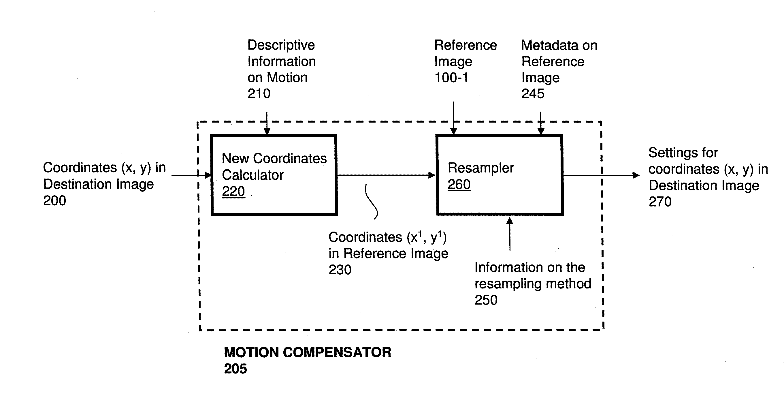
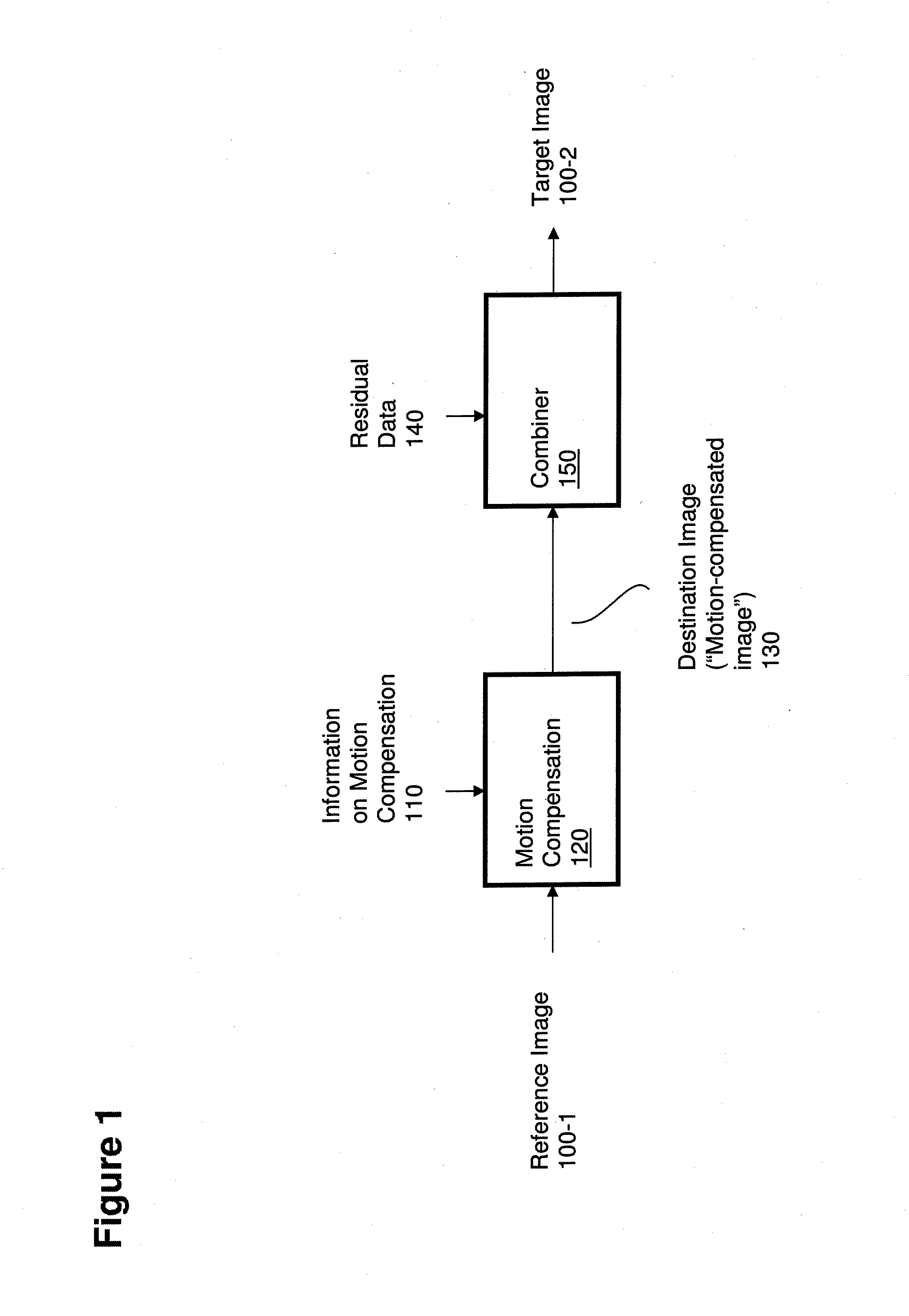
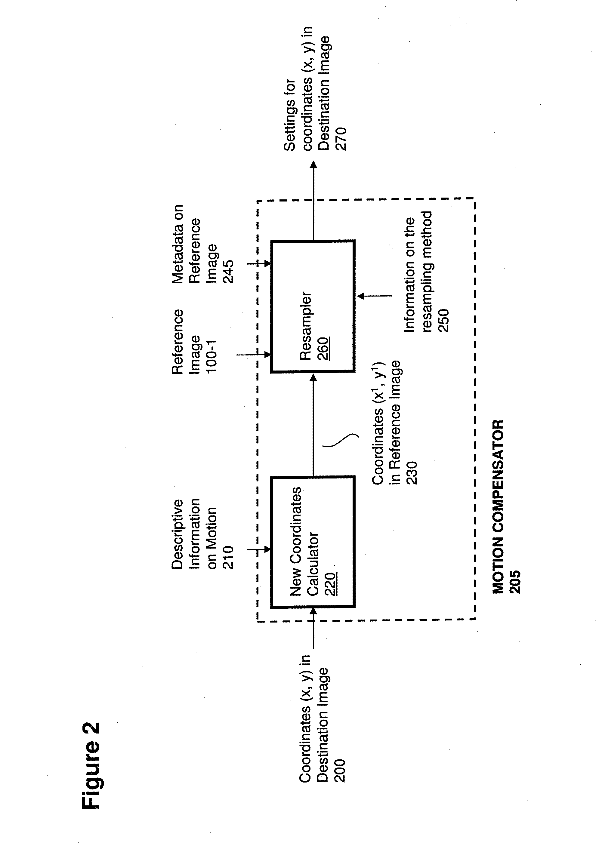
[0098]Methods illustrated herein are suitable for any type of multi-dimensional signals, including without limitation sound signals, multichannel sound signals, pictures, two-dimensional images, video signals, multi-view video signals, 3D video signals, volumetric signals, volumetric video signals, medical imaging signals, signals with more than four dimensions, etc.

[0099]For simplicity, along the description the illustrated embodiments usually adopt the use case of motion zones used in the context of motion compensation operations for the encoding and decoding of video sequences, i.e., time-based signals consisting of a sequence of 2D images (commonly called “frames”, or “fields” in the case of interlaced video signals), with each element (in such non-limiting example case typically referred to as “pixel”) being characterized by a set of color settings in a suitable color space (e.g., YUV, RGB, HSV, etc.). Different color planes (e.g., the luminance-Y plane and the two chrominance—...


PUM


Abstract

Computer processor hardware receives settings information for a first image. The first image includes a set of multiple display elements. The computer processor hardware receives motion compensation information for a given display element in a second image to be created based at least in part on the first image. The motion compensation information indicates a coordinate location within a particular display element in the first image to which the given display element pertains. The computer processor hardware utilizes the coordinate location as a basis from which to select a grouping of multiple display elements in the first image. The computer processor hardware then generates a setting for the given display element in the second image based on settings of the multiple display elements in the grouping.

Description

RELATED APPLICATIONS[0001]This application is related and claims the benefit of U.S. Provisional Patent Application Ser. No. 61 / 646,797 entitled “SIGNAL ENCODING, DECODING AND RECONSTRUCTION OF TIME-BASED AND / OR MULTIDIMENSIONAL SIGNALS BASED ON MULTIDIMENSIONAL TIER-BASED INHERITANCE” (Attorney Docket No. VNO12-01p), filed on May 14th, 2012, the entire teachings of which are incorporated herein by this reference.[0002]This application is related to and claims the benefit of U.S. Provisional Patent Application Ser. No. 61 / 647,426 entitled “ESTIMATION, ENCODING, DECODING AND USAGE OF MOTION INFORMATION IN MULTIDIMENSIONAL SIGNALS THROUGH MOTION ZONES, MOTION MATRIXES, WARP MAPS AND MOTION TRANSFORMS” (Attorney Docket No. VNO12-02p), filed on May 15th, 2012, the entire teachings of which are incorporated herein by this reference.[0003]This application is also related to U.S. patent application Ser. No. 13 / 188,188 entitled “INHERITANCE IN A TIERED SIGNAL QUALITY HIERARCHY,” (Attorney D...

Claims


Application Information

Patent Timeline
Patent Type & Authority Applications(United States)
IPC IPC(8): G06T7/20H04N19/94
CPCG06T7/204H04N19/63H04N19/62H04N19/635H04N19/23H04N19/33H04N19/87H04N19/94H04N19/59H04N19/126H04N19/30H04N19/42H04N19/439G06T7/248H04N19/70H04N19/50H04N19/51H04N19/40H04N19/57H04N19/573G06T9/00G06T9/40H04N5/145H04N19/136
Inventor ROSSATO, LUCAMEARDI, GUIDO
Owner V NOVA INT LTD
Why Eureka
Try Eureka