Communication system

a communication system and communication system technology, applied in the field of communication systems, can solve the problems of radio link failure (rlf), not disclose, and involve collision risks, and achieve the effect of stabilizing the operation of the communication system

Inactive Publication Date: 2013-12-05
MITSUBISHI ELECTRIC CORP
View PDF4 Cites 34 Cited by
  • Summary
  • Abstract
  • Description
  • Claims
  • Application Information

AI Technical Summary

Benefits of technology

[0100]According to the communication system of the present invention, the operation as a communication system can be stabilized while improving a data rate using carrier aggregation, which enables to appropriately provide services.
[0101]These and other objects, features, aspects and advantages of the present invention will become more apparent from the following detailed description of the present invention when taken in conjunction with the accompanying drawings.

Problems solved by technology

The RACH involves a collision risk.
Re-establishment is triggered when the PCell results in a radio link failure (RLF).
However, Non-Patent Document 10 does not describe the method of notifying user equipments of the configuration content.
Also, Non-Patent Document 10 does not pose a problem with the relationship between the CSG to which the SCell belongs and the CSG to which the user equipment belongs, and does not disclose a solution thereto.
Also, Non-Patent Document 2 does not pose a problem with the relationship between the CSG to which the SCell belongs and the CSG to which the user equipment belongs, and does not disclose a solution thereto.

Method used


Image

  • Communication system
  • Communication system
  • Communication system

Examples


first embodiment

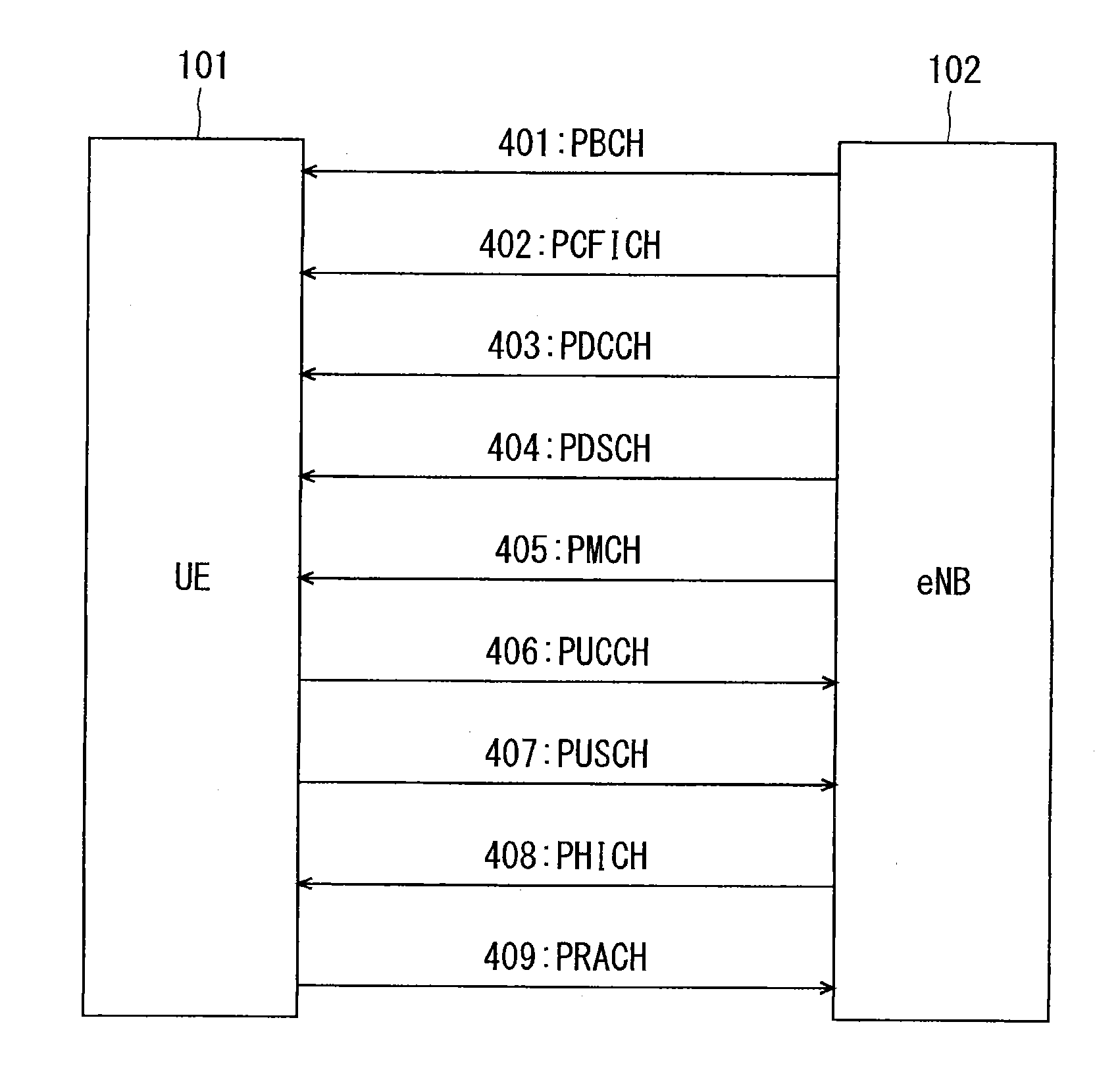
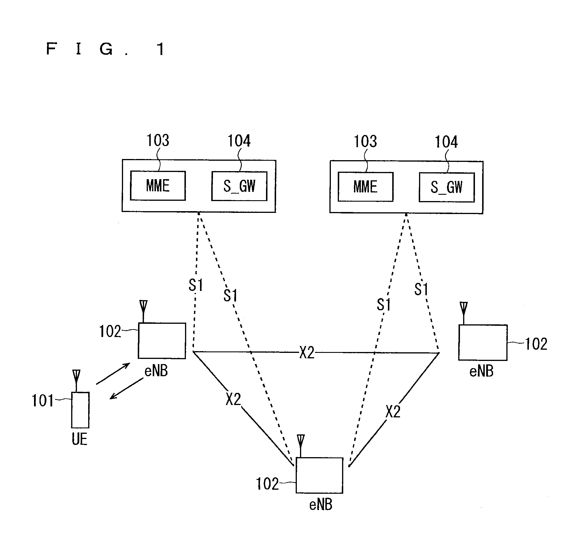
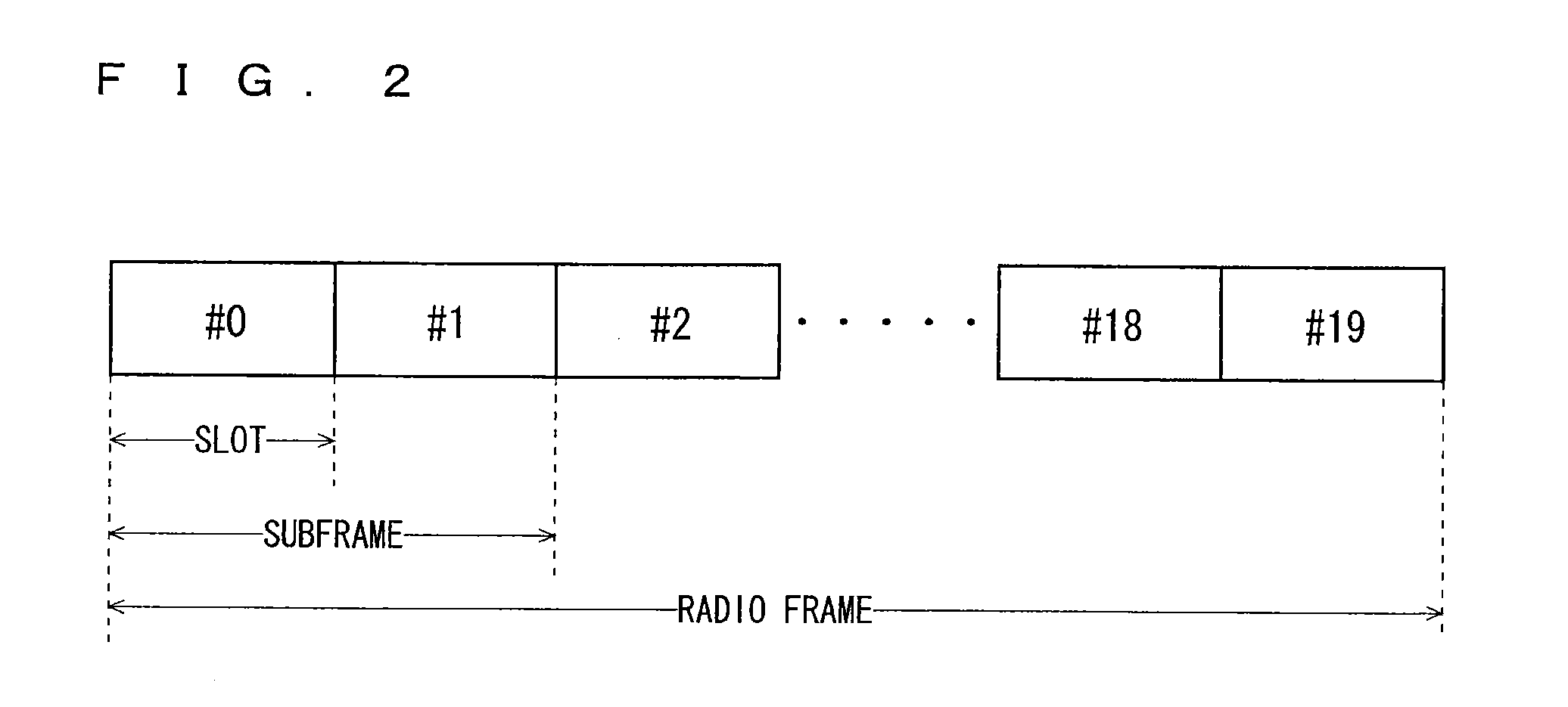
[0129]FIG. 7 is a block diagram showing an overall configuration of an LTE mobile communication system, which is currently under discussion of 3GPP. Currently, an overall system configuration including closed subscriber group (CSG) cells (Home-eNodeBs (Home-eNB; HeNB) of E-UTRAN, Home-NB (HNB) of UTRAN) and non-CSG cells (eNodeB (eNB) of E-UTRAN, NodeB (NB) of UTRAN, and BSS of GERAN) is studied in 3GPP and, as to E-UTRAN, the configuration as shown in FIG. 7 is proposed (see Chapter 4.6.1 of Non-Patent Document 1).

[0130]FIG. 7 is described. A user terminal device (hereinafter, referred to as “user equipment” or “UE”) 71 is capable of performing radio communication with a base station device (hereinafter, referred to as “base station”) 72 and transmits / receives signals through radio communication. The user terminal device is equivalent to a communication terminal device. The base stations 72 are classified into an eNB 72-1 that is a macro cell and a Home-eNB 72-2 that is a local nod...

second embodiment

[0177]A problem to be solved in a second embodiment is described below. In a case where the first embodiment is used, the following problem occurs. As described above, in access from a user equipment through a CSG cell, an MME performs access control, that is, restricts access from a UE to a CSG cell. That is, a base station does not restrict access to the CSG. As a result, for a UE unregistered with the CSG to which a cell belongs, the cell (CC) may be configured as a SCell to become active.

[0178]Therefore, in a communication system, the following problem occurs if an MME performs access control in access from a user equipment through a CSG cell. Considered here is a case in which a base station configures, for a user equipment unregistered with a CSG to which a cell belongs, the cell as a SCell. In this case, after the cell is configured as a SCell, access from the user equipment through the cell is not permitted through access control by the MME. In such a case, carrier aggregati...

third embodiment

[0262]A problem to be solved in a third embodiment is described below. In a case where the second embodiment described above is used, the following problem occurs. A CSG is a cell for specific subscribers, in which subscribers who are allowed to use can be specified by an operator. This leads to a problem that the second embodiment in which the user equipment unregistered with the CSG to which a cell belongs uses a resource of the cell contradicts the gist of the CSG.

[0263]As to the CSG cell, such an operation that CSG members belonging to the same CSG are preferentially provided with services is studied. Specific examples of the preferential treatment include the preferential allocation of resources to CSG members and discount of communication costs for CSG members. Along with this, the charging setting may differ between the CSG members and non-CSG members.

[0264]In a case where the second embodiment is used, if the user which belongs to a CSG wishes to receive some services or app...


PUM


Abstract

The present invention has an object to provide a communication system capable of appropriately providing services while improving a data rate using carrier aggregation. In Step ST1408, of a cell1 and a cell2 of a base station A, RRC connection is established between the cell1 and a UE, and the cell1 becomes a primary cell (PCell). Then, in Step ST1418, the cell1 determines to configure the cell2 as a secondary cell (SCell) to be aggregated with the own cell. Then, the cell1 notifies the UE of the above in Step ST1419. Upon this notification, the operation of restricting access to the cell2 from the UE is stopped by an MME, and thereafter, communication between the UE and the cell2 is started in Step ST1422.

Description

TECHNICAL FIELD[0001]The present invention relates to a communication system in which a base station device performs radio communication with a plurality of communication terminal devices.BACKGROUND ART[0002]Commercial service of a wideband code division multiple access (W-CDMA) system among so-called third-generation communication systems has been offered in Japan since 2001. In addition, high speed downlink packet access (HSDPA) service for achieving higher-speed data transmission using a downlink has been offered by adding a channel for packet transmission (high speed-downlink shared channel (HS-DSCH)) to the downlink (dedicated data channel, dedicated control channel). Further, in order to increase the speed of data transmission in an uplink direction, service of a high speed uplink packet access (HSDPA) system has been offered. W-CDMA is a communication system defined by the 3rd generation partnership project (3GPP) that is the standard organization regarding the mobile communi...

Claims


Application Information

Patent Timeline
Patent Type & Authority Applications(United States)
IPC IPC(8): H04W76/02
CPCH04W76/025H04L5/0098H04W48/08H04L5/001H04W84/045H04W48/20H04W48/16H04W76/15H04W24/02H04W48/02
Inventor MAEDA, MIHOMOCHIZUKI, MITSURU
Owner MITSUBISHI ELECTRIC CORP
Why Eureka
Try Eureka