Method and apparatus for separation of mixture

a technology of mixture and separation method, which is applied in the direction of magnetic separation, solid separation, chemistry apparatus and processes, etc., can solve the problems of large-scale system and complicated system that are necessary to realize this method, and achieve the effect of accurately separating a specific type of particle and accurately separating the mixture by typ

Inactive Publication Date: 2013-12-12
UBE IND LTD
View PDF5 Cites 4 Cited by
  • Summary
  • Abstract
  • Description
  • Claims
  • Application Information

AI Technical Summary

Benefits of technology

[0013]In the present invention, the magnetic field gradient of the magnetic field that is to be applied to the particles contained in the mixture and to the supporting liquid has a horizontal component in addition to a vertical component. Accordingly, a horizontal force resulting from this magnetic field is applied to paramagnetic or diamagnetic particles contained in the mixture, and these particles are guided to a predetermined height from the bottom face of the separating tank while horizontally traveling from the placing or introducing location to the collecting location, or horizontally travel from the placing location to the collecting location while magnetically levitating at the liquid surface of the supporting liquid. Since the trajectories of the particles in the supporting liquid vary depending on the physical properties of the particles, the magnetic or diamagnetic particles and the other particles contained in the mixture are positioned at vertically different heights between the bottom face of the separating tank and the liquid surface of the supporting liquid.
[0014]In this manner, according to the present invention, the particles in the mixture are caused to travel from the location for placing into the supporting liquid to the collecting location by the magnetic force, and thus, it is possible to collect the separated particles while the mixture is being introduced into the supporting liquid. Furthermore, the supporting liquid does not have to flow along in order to cause the particles to travel, and thus, it is possible to accurately separate the mixture by type, or to accurately separate a specific type of particle from the mixture.

Problems solved by technology

The method disclosed in Patent Document 1 employs a plurality of separators, tanks, and the like in order to realize the above-described separating processes, and thus, a complicated and large-scale system is necessary for realizing this method.

Method used


Image

  • Method and apparatus for separation of mixture
  • Method and apparatus for separation of mixture
  • Method and apparatus for separation of mixture

Examples


example 1

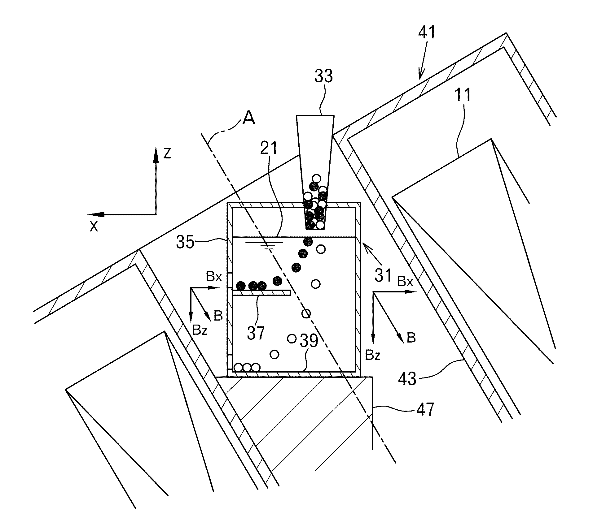
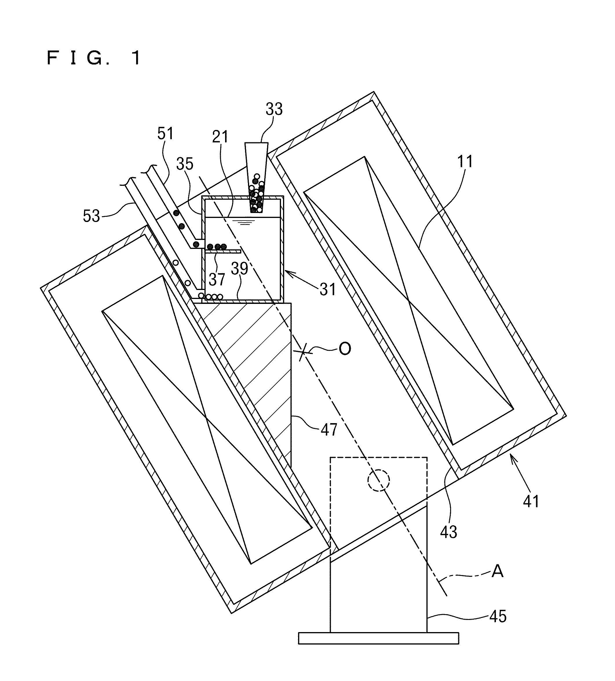
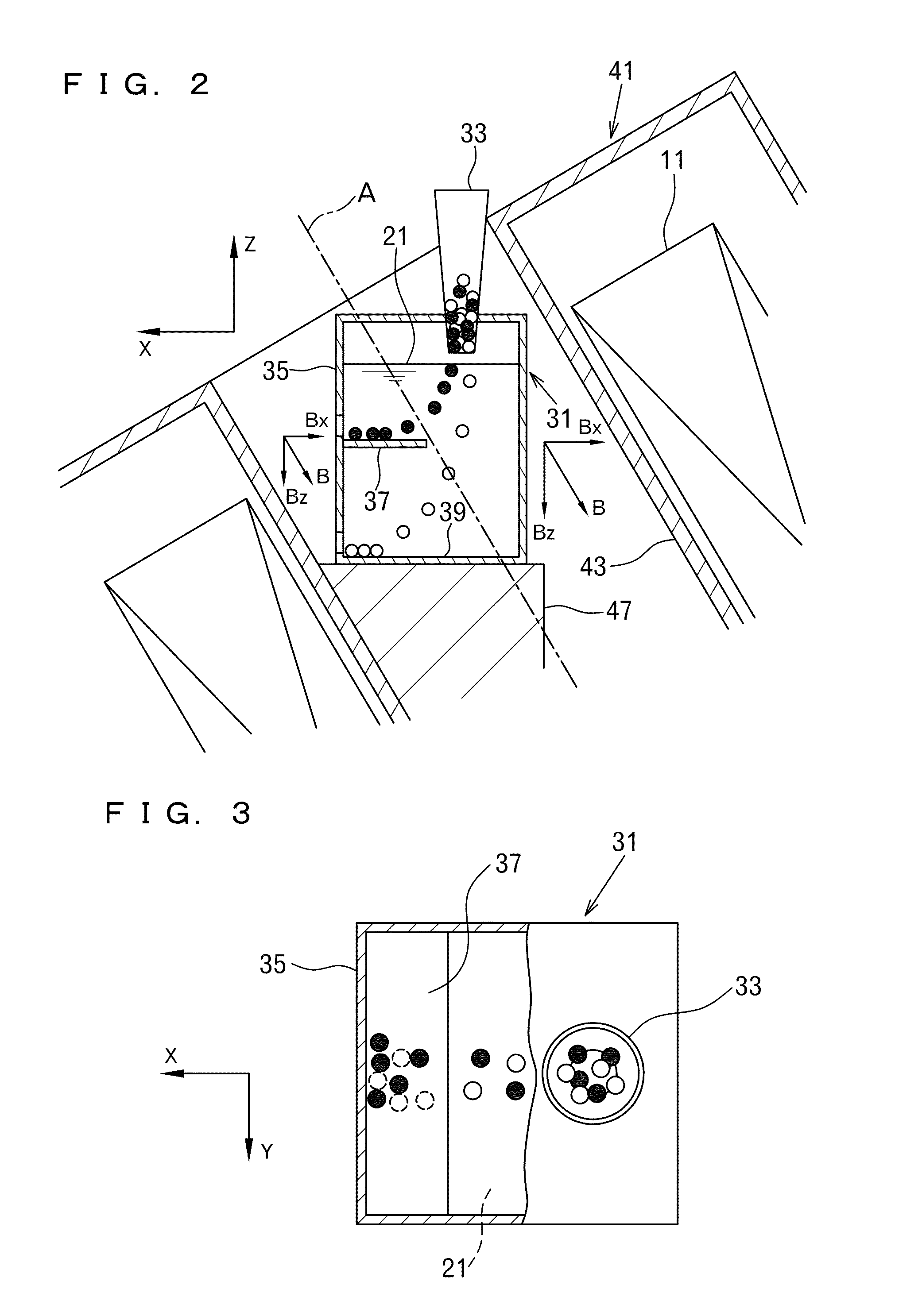
[0072]A superconducting magnet using a solenoid coil having a bore size of 100 mm was disposed such that the coil central axis was inclined by 30 degrees with respect to the vertical direction. As shown in FIGS. 1 and 2, a separating tank storing a 50 wt % aqueous solution of manganese chloride as the supporting liquid was disposed in the internal space surrounded by the superconducting magnet. The separating tank was made of transparent carbonate, and had a shape as shown in FIGS. 1 to 3. The separating tank had a width of 40 mm, a length of 40 mm, and a height of 50 mm, and a shelf board having a width of 15 mm was provided so as to project at a height of 25 mm from the bottom face.

[0073]A mixture of glass (silica) particles (diamagnetic substance) and alumina particles (diamagnetic substance) was prepared (see Table 1 for the density and the volume susceptibility of the glass (silica) and the alumina), electricity was supplied to the superconducting magnet, so that a magnetic fie...

example 2

[0075]FIGS. 9(a) and 9(b) are explanatory views schematically illustrating the outline of Example 2 corresponding to the third embodiment described above. A separating tank (71) approximately in a U shape was manufactured from transparent carbonate. The separating tank (71) had a length of 70 mm, a height of 60 mm, and a width of 2 mm, and a horizontal shelf board (73) was provided at a height of 10 mm from the bottom face. Extending portions (75a) and (75b) at both ends of the separating tank (71) had open upper ends. One of the extending portions, i.e., the extending portion (75b), was provided with a vertical partition plate (77) that was linked to the shelf board (73). The separating tank (71) stored a 50 wt % aqueous solution of manganese chloride as a supporting liquid (79).

[0076]A mixture of aluminum particles (paramagnetic substance) and titanium particles (paramagnetic substance) was prepared (see Table 1 for the density and the volume susceptibility of the aluminum and the...

example 3

[0080]Treatment was performed as in Example 2, except that the mixture of glass particles and alumina particles of Example 1 was used, and that a 15 wt % aqueous solution of cobalt chloride was used as the supporting liquid (79). The glass particles and the alumina particles floated due to the magneto-Archimedes effect at mutually different heights as shown in FIG. 9(a), and then traveled in the horizontal direction (in the radial direction) while sinking in the supporting liquid (79) as shown in FIG. 9(b), after which the glass particles were positioned on the shelf board (73), and the alumina particles were positioned on the bottom face of the separating tank (71), as shown in the photograph in FIG. 12(a).


PUM

PropertyMeasurementUnit
densityaaaaaaaaaa
volume susceptibilityaaaaaaaaaa
magnetic fieldaaaaaaaaaa

Abstract

The present invention provides a method and an apparatus capable of continuously and accurately separating, by type, a mixture containing at least two types of particles, or capable of separating specific particles from the mixture, using a gradient magnetic field. In the present invention, a mixture containing at least two types of particles, particles of one type of which are made of a paramagnetic or diamagnetic substance, is treated. A magnetic field whose magnetic field gradient has a vertical component and a horizontal component is applied to a supporting liquid 21 stored in a separating tank 31. When the mixture is placed into the supporting liquid 21, the particles of the one type are guided such that they are positioned in the supporting liquid 21 at a predetermined height from a bottom face 39 of the separating tank 31 while horizontally traveling. Alternatively, the particles of the one type magnetically levitate at a liquid surface of the supporting liquid 21 and horizontally travel. Particles of another type of the at least two types of particles are positioned at a position vertically different from that of the particles of the one type, between the bottom face 39 of the separating tank 31 and the liquid surface of the supporting liquid 21.

Description

FIELD OF THE INVENTION[0001]The present invention relates to a mixture separating method and a mixture separating apparatus for separating, by substance type, a mixture containing a plurality of types of substances, or for separating a specific type of substance from the mixture, using a magnetic field having a magnetic field gradient.BACKGROUND OF THE INVENTION[0002]When collecting metals or resins from waste such as a used electronic product including the metals or resins as the builders, typically, various separating processes are performed on a mixture of different types of substances obtained by grinding the waste or part thereof. For example, Patent Document 1 (JP 2010-524663A discloses a recycling method, including a process that places shredder residue obtained from waste into a sink-float tank, and separates the residue into metal residue and plastic residue using the difference in density or specific gravity, a process that separates, by type, the metal residue using an ai...

Claims


Application Information

Patent Timeline
Patent Type & Authority Applications(United States)
IPC IPC(8): B03C1/02
CPCB03C1/02B03C1/0335B03C1/288B03C1/32B03C2201/18B03B5/30B03B5/44
Inventor NISHIJIMA, SHIGEHIROMISHIMA, FUMIHITO
Owner UBE IND LTD
Why Eureka
Try Eureka