

Current Shunt
a current shunt and current technology, applied in the field of current shunt, can solve the problems of large dynamic range, large error in the ultimate derived value of the measured current, and inability to accurately measure current, etc., and achieve the effect of reducing or eliminating the error in the derived current valu
- Summary
- Abstract
- Description
- Claims
- Application Information
AI Technical Summary
Benefits of technology
Problems solved by technology
Method used
Image

Examples
Embodiment Construction
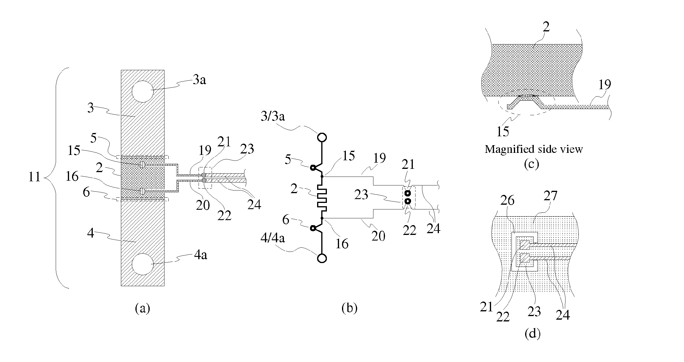
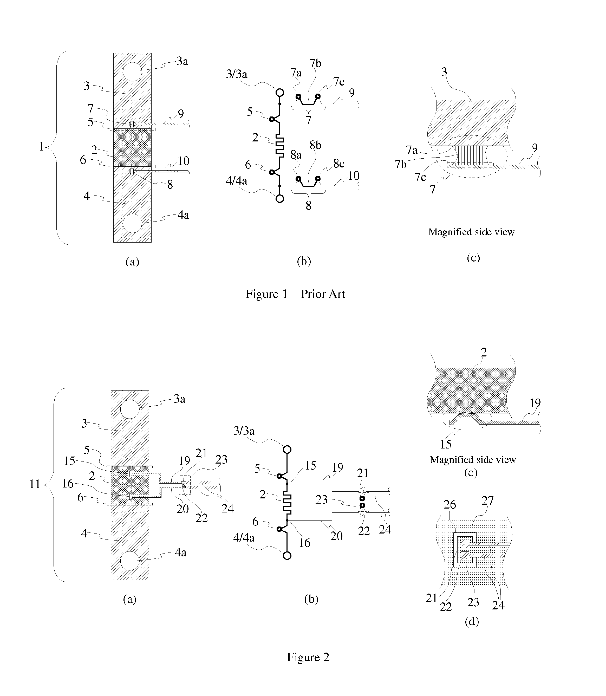
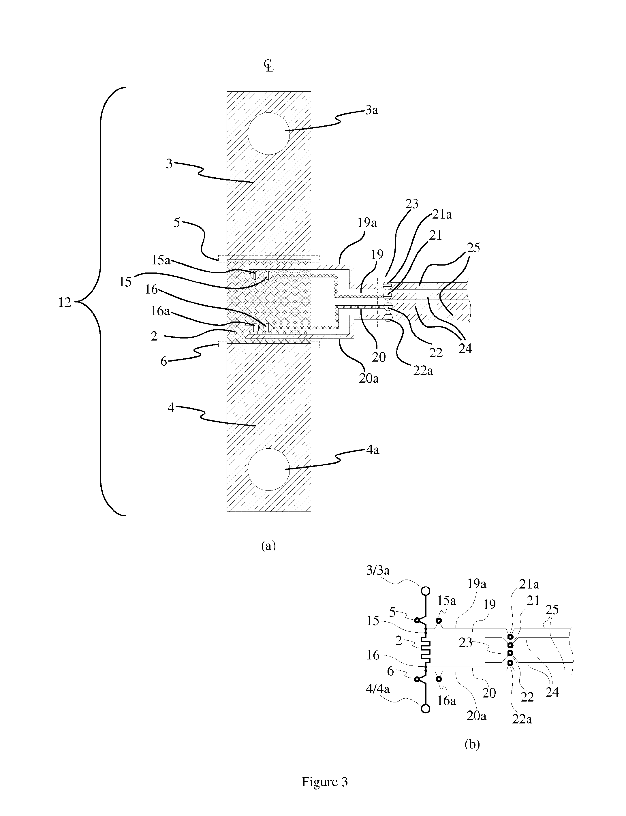
[0020]One purpose of the invention is to reduce the errors associated with thermoelectric voltages in the current shunt. In the simplest form (referring to FIGS. 2a and 2b), the method according to this invention requires simultaneous fulfillment of several requirements, namely:[0021]a.) Connecting points 15 / 16 for the sense lines 19 / 20 must be located on the element 2 of the shunt 11 (and not on the elements 3 / 4 as in the previous art).[0022]b.) Material of the sense lines 19 / 20 must be the same as the material of the resistive element 2.[0023]c.) The attachment technique between the element 2 and sense lines 19 / 20 must not introduce any other materials into the joint. A preferred method of attachment will soften and liquefy small adjacent areas of both element 2 and sense lines 19 / 20; after cooling down element 2 and sense lines 19 / 20 will remain attached to each other and will maintain low resistance of the attachment points, as illustrated in FIG. 2c. Suitable industrial process...
PUM
 Abstract
Description
Claims
Application Information