
Casting method for obtaining a part including a tapering portion

a technology of casting method and tapering portion, which is applied in the direction of machine/engine, foundry pattern, foundry moulding apparatus, etc., can solve the problems of material gaps in the end of the tapering portion, material not being cast, and not being able to spread, etc., to achieve the effect of easy production, high quality and less cos

Active Publication Date: 2013-12-12
SN DETUDE & DE CONSTR DE MOTEURS DAVIATION S N E C M A
View PDF4 Cites 8 Cited by
  • Summary
  • Abstract
  • Description
  • Claims
  • Application Information

AI Technical Summary

Benefits of technology

The patent describes a method to create a raw casting with two different parts. This allows for the creation of a tapering part that has specific aerodynamic properties, without the need for additional machining steps. The method also reduces the number of manual steps and the technical difficulty of the process, making it easier and less expensive to produce. The invention also includes a turbine engine blade that does not require any reworking or tapering of its trailing edge after casting, making it easier and less expensive to produce.

Problems solved by technology

Casting is the technique that is in the most widespread use at present for making parts of this type, and in prior art casting techniques it is not possible to obtain such tapering parts in reliable manner.
Below a certain thickness, the material being cast does not manage to spread throughout the entire volume of the mold, and most particularly into the narrowest interstices, and that leads to gaps of material in the ends of the tapering portions of the part.
Under such circumstances, it is possible to select a material that provides better castability, but such a change in the material is generally to the detriment of other properties, in particular such as the mechanical strength or the high temperature performance of the part.
In addition, such a material may be more expensive.
Nevertheless, such centrifugal molds are expensive and more difficult to operate, thus requiring the entire casting method to be revised.

Method used


Image

  • Casting method for obtaining a part including a tapering portion
  • Casting method for obtaining a part including a tapering portion
  • Casting method for obtaining a part including a tapering portion

Examples


first embodiment

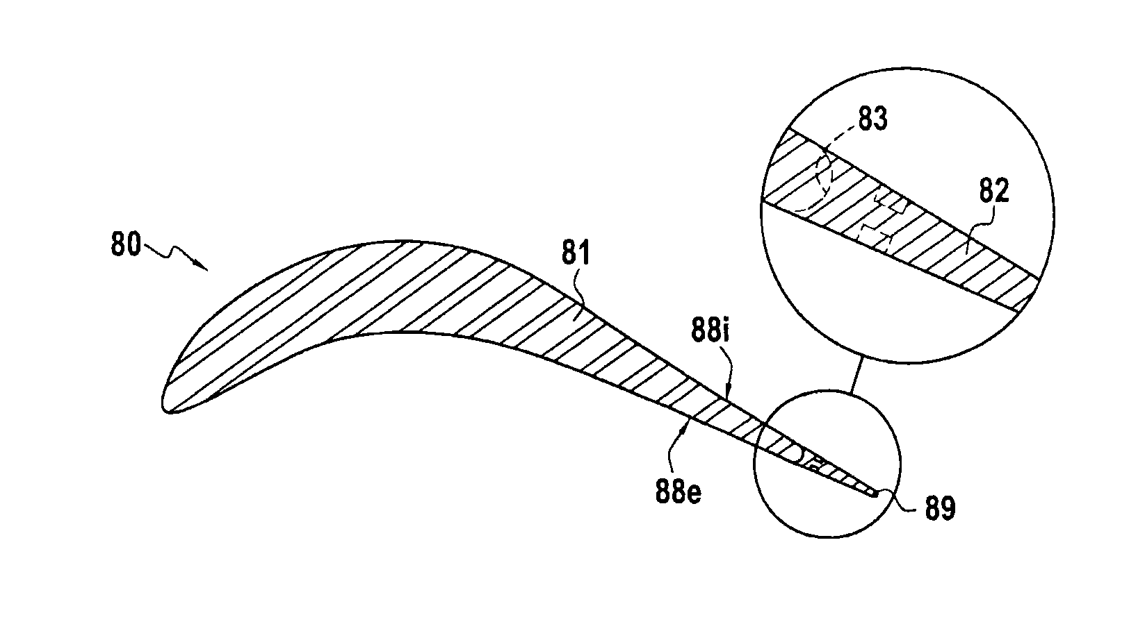
[0053]Thus, FIG. 1H shows a turbine blade obtained by casting and having a tapering trailing edge. In this example, the insert portion 82 reproduces the complete shape of the trailing edge extending the pressure side 88i and the suction side 88e of the blade to a common end 89; its thickness is then about 0.7 mm and it decreases down to its end 89.

second embodiment

[0054]FIG. 2 shows a turbine blade obtained by casting and having a tapering trailing edge. In this second example, the insert portion is a fine flat plate 182 having a thickness of 0.3 mm and arranged to extend the suction side 88e of the blade.

[0055]FIG. 3 shows a third embodiment of a turbine blade obtained by casting and having a tapering trailing edge. In this third embodiment, the insert portion comprises a first fine flat plate 282a having a thickness of 0.3 mm arranged to extend the suction side 88e of the blade, and a second fine flat plate 282b having a thickness of 0.3 mm and arranged to extend the pressure side 88i of the blade.

[0056]the implementations and embodiments described herein are given by way of non-limiting illustration, and on the basis of this description, a person skilled in the art can easily modify these implementations and embodiments or can envisage others, while remaining within the scope of the invention.

[0057]Furthermore, the various characteristics ...


PUM

PropertyMeasurementUnit
Thicknessaaaaaaaaaa
Temperatureaaaaaaaaaa
Shapeaaaaaaaaaa

Abstract

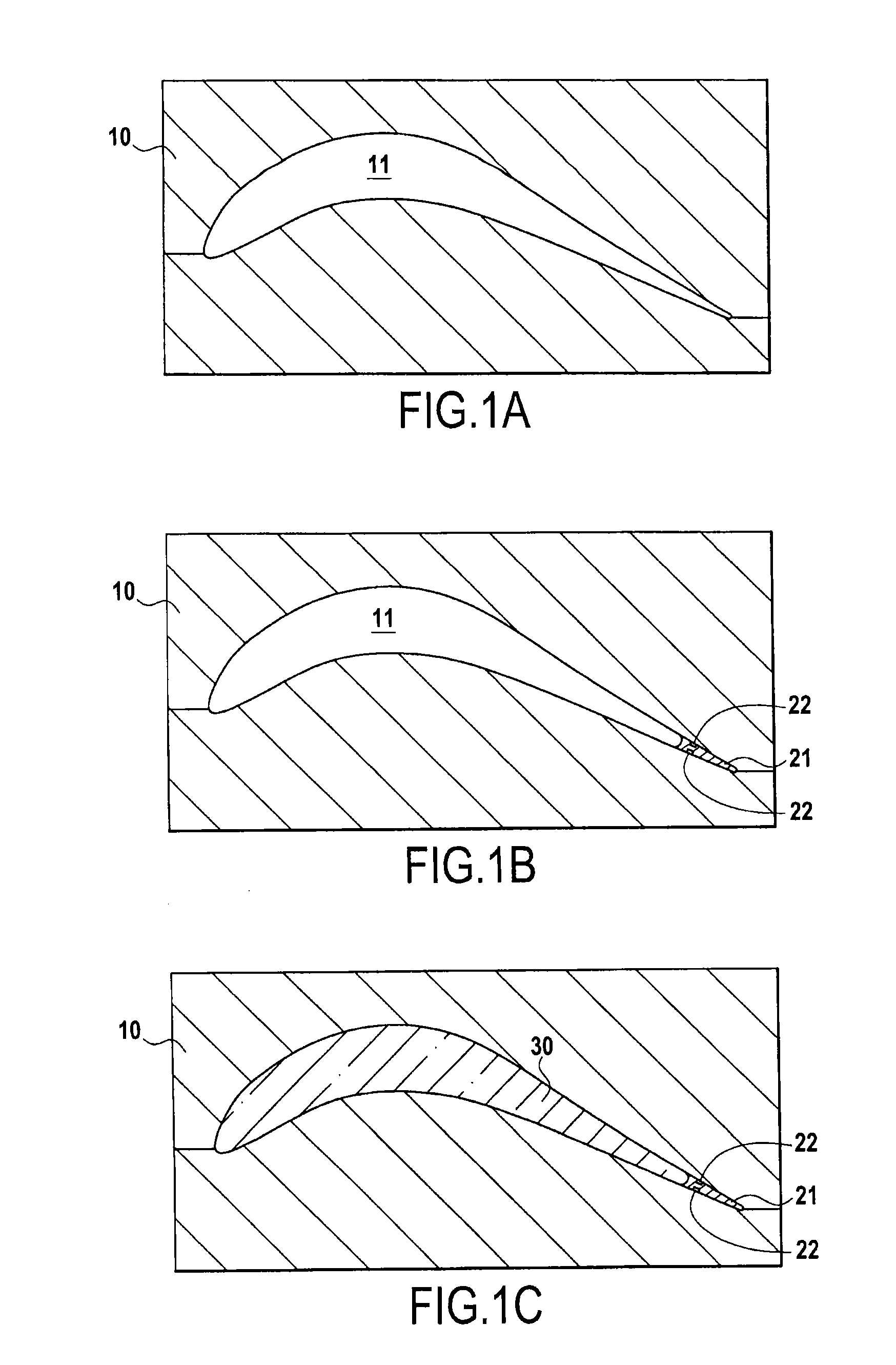
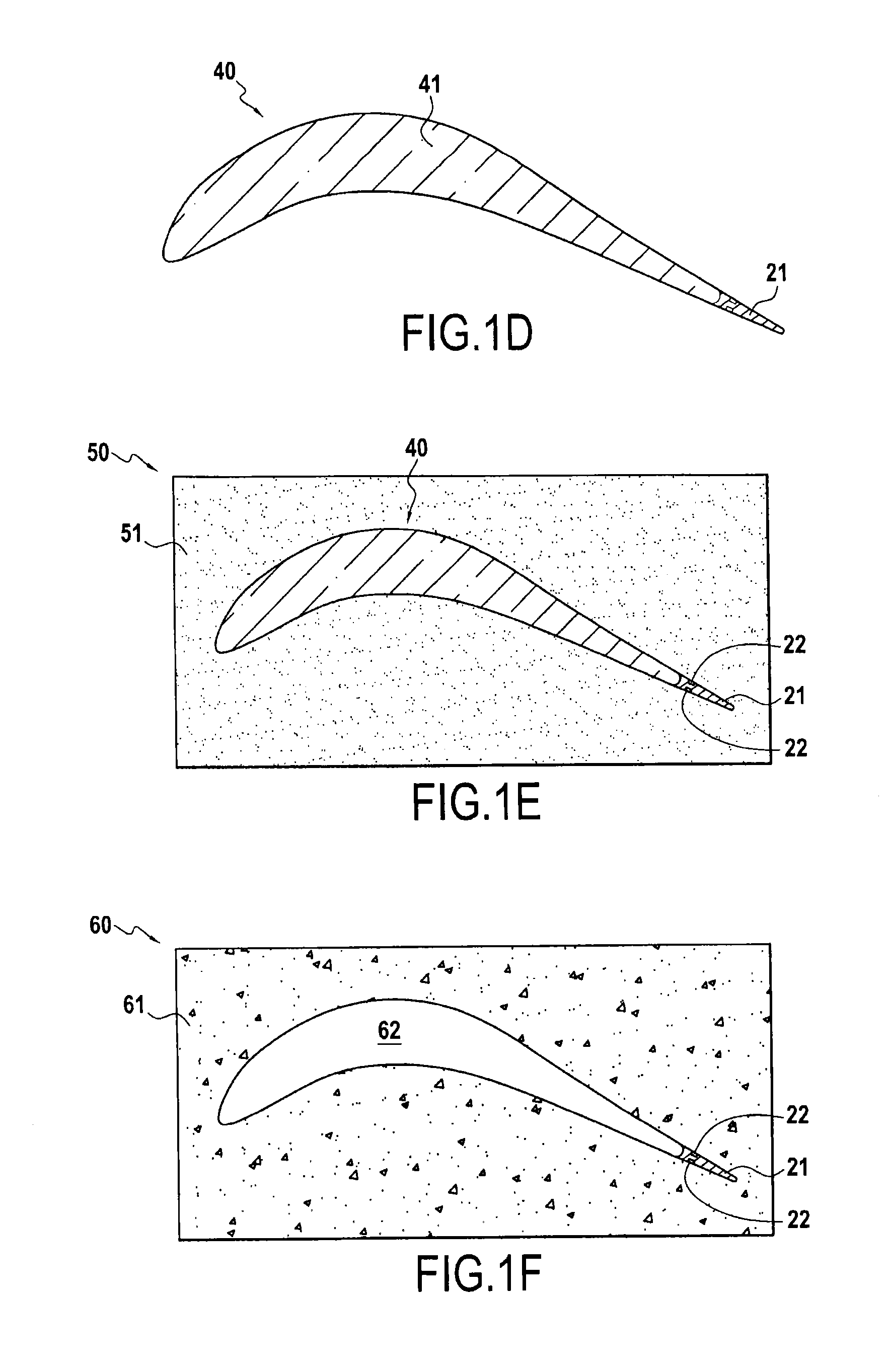
A casting method for obtaining a part that includes a tapering portion, and also a turbine engine blade obtained by casting and including a tapering trailing edge. According to the invention, the method comprises the following steps: providing an insert element having a tapering portion; making a shell around the insert element; and casting a molten material into said shell including the insert element.

Description

FIELD OF THE INVENTION[0001]The present description relates to a casting method for obtaining a part that includes a tapering portion, and also to a turbine engine blade obtained by casting and including a tapering trailing edge.[0002]Such a casting method may be used for obtaining a tapering part without gaps of material appearing on unmolding. It is thus possible by casting to produce parts that are highly tapered, such as turbine engine blades presenting fine trailing edges that procure high aerodynamic performance, or to produce other complex tapering parts of the kind that may be of use in the field of aviation, for example.STATE OF THE PRIOR ART[0003]Certain industries require parts to be produced that include highly tapered portions making it possible to procure certain properties for such parts or their environment. For example, in a turbine engine, it is known that the fineness of the trailing edges of turbine blades has a strong influence on their aerodynamic properties, a...

Claims


Application Information

Patent Timeline
IPC IPC(8): B22D25/02F01D5/14B22C9/04
CPCB22D25/02B22C9/043F01D5/147B22C7/02B22C9/04B22C9/24B22D19/0072B22D19/04F05D2230/21F05D2240/304
Inventor DIGARD BROU DE CUISSART, SEBASTIENBASSERY, JOSSERANDDEFLANDRE, STEPHANIE
Owner SN DETUDE & DE CONSTR DE MOTEURS DAVIATION S N E C M A
Learn More