
Systems which Determine Operating Parameters and Disinfection Schedules for Germicidal Devices and Germicidal Lamp Apparatuses Including Lens Systems

a technology of operating parameters and disinfection schedules, which is applied in the field of germicidal devices, can solve the problems of wasting time and/or energy, difficult to treat, and many conventional room/area decontamination systems are limited

Active Publication Date: 2013-12-12
XENEX DISINFECTION SERVICES
View PDF3 Cites 94 Cited by
  • Summary
  • Abstract
  • Description
  • Claims
  • Application Information

AI Technical Summary

Benefits of technology

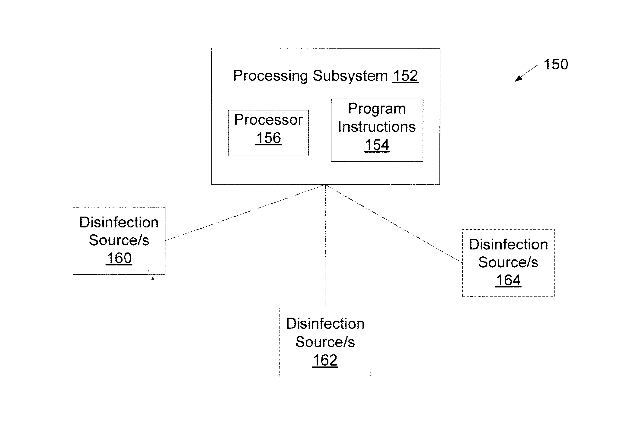
The patent describes systems and apparatuses for disinfecting a room by using a germicidal lamp and a processing subsystem. The processing subsystem receives data about the physical attributes of the room and determines the best location and orientation for positioning the disinfection source based on that data. The systems also allow for multiple disinfection sources, where the processing subsystem receives data about the characteristics of the room and determines individual operating parameters for each disinfection source. The processing subsystem can also compare target locations, regions, objects, or surfaces and execute corrective actions if necessary. The technical effect of the patent is to provide an efficient and effective way to disinfect a room by using a germicidal lamp and a processing subsystem to optimize the disinfection process.

Problems solved by technology

This is especially important as antimicrobial resistant organisms are more commonly found in environments and are becoming increasingly difficult to treat.
A challenge with conventional room / area decontaminations systems is getting a germicidal agent distributed in an efficient manner to all surfaces which need to be disinfected.
In particular, many conventional room / area decontamination systems are limited in the number of disinfection sources they include due to cost and size restraints.
A problem with a high dose blanket distribution of a germicidal agent is that some portions of a room or area may be overexposed, which effectively is a waste of the germicidal agent and potentially a waste of time and / or energy to perform a disinfection process.
Furthermore, in some cases, portions of a room / area may not receive enough of a germicidal agent when the germicidal agent is blanket distributed throughout a room, particularly surfaces which are a relatively far distance from a disinfection source and / or which are not in direct line with a disinfection source.
Underexposure of a germicidal agent can leave a surface or object with an undesirably high number of pathogenic microorganisms, leaving persons in subsequent contact with the surfaces highly susceptible to infection.
A further problem with conventional room / area decontamination systems is a lack of consideration and precedence of objects and surfaces in a room in performing a disinfection process.
As a consequence, if a disinfection process for a room / area is terminated before its allotted time, there is potential that objects and / or surfaces within the room which are likely to be highly contaminated will not have been adequately disinfected.
In some embodiments, a disinfection source of a room / area decontamination system may be positioned near an object or surface, such as a bed in a hospital room, but positioning a disinfection source near a particular object does not address disinfection needs of other objects or surfaces within a room / area considered likely to be highly contaminated, such as a door handle or a light switch in a room.
Furthermore, when a disinfection source is fixedly installed in a particular position within a room, the effect of its location to a particular object is rendered moot if the object is moved.
In cases in which a decontamination system includes disinfection source / s which are freely positionable within a room, the task of positioning the disinfection source / s is generally manual and, thus, is labor intensive and prone to placement error.
Although different types of discharge lamps have been investigated to provide UV light for different applications, little has been done to improve the efficiency of the ultraviolet light generated in apparatuses having discharge lamps, particularly with respect to the propagation of the ultraviolet light (i.e., distance and angle of incidence on a target object), the intensity of the ultraviolet light, and the duration of exposure of the ultraviolet light.
A reason for such a lack of advancement is that many apparatuses having discharge lamps, such as food sterilization and single object disinfection devices, are configured to treat items placed in close proximity and in direct alignment with the lamp and, thus, little or no improvement in efficiency of the UV light may be realized by altering its propagation.
Moreover, room / area decontamination systems are specifically designed to disperse light over a vast area and, thus, altering UV propagation from a system may hinder such an objective.
In addition, many apparatuses with discharge lamps are limited in application and versatility.
For instance, many food sterilization and single object disinfection devices are self-contained apparatuses and are configured for treatment of specific items and, thus, do not generally include features which improve the versatility of the systems for treatment for other items or use in other applications.
Furthermore, some apparatuses require time consuming and / or cumbersome provisions in order to protect a user from harm.
Exposure of the visible light and the ultraviolet light may be harmful and, thus, provisions such as containing the pulsed light within the confines of the apparatus or shielding windows of a room in which a room decontamination unit is used may be needed.

Method used


Image

  • Systems which Determine Operating Parameters and Disinfection Schedules for Germicidal Devices and Germicidal Lamp Apparatuses Including Lens Systems
  • Systems which Determine Operating Parameters and Disinfection Schedules for Germicidal Devices and Germicidal Lamp Apparatuses Including Lens Systems
  • Systems which Determine Operating Parameters and Disinfection Schedules for Germicidal Devices and Germicidal Lamp Apparatuses Including Lens Systems

Examples


Embodiment Construction

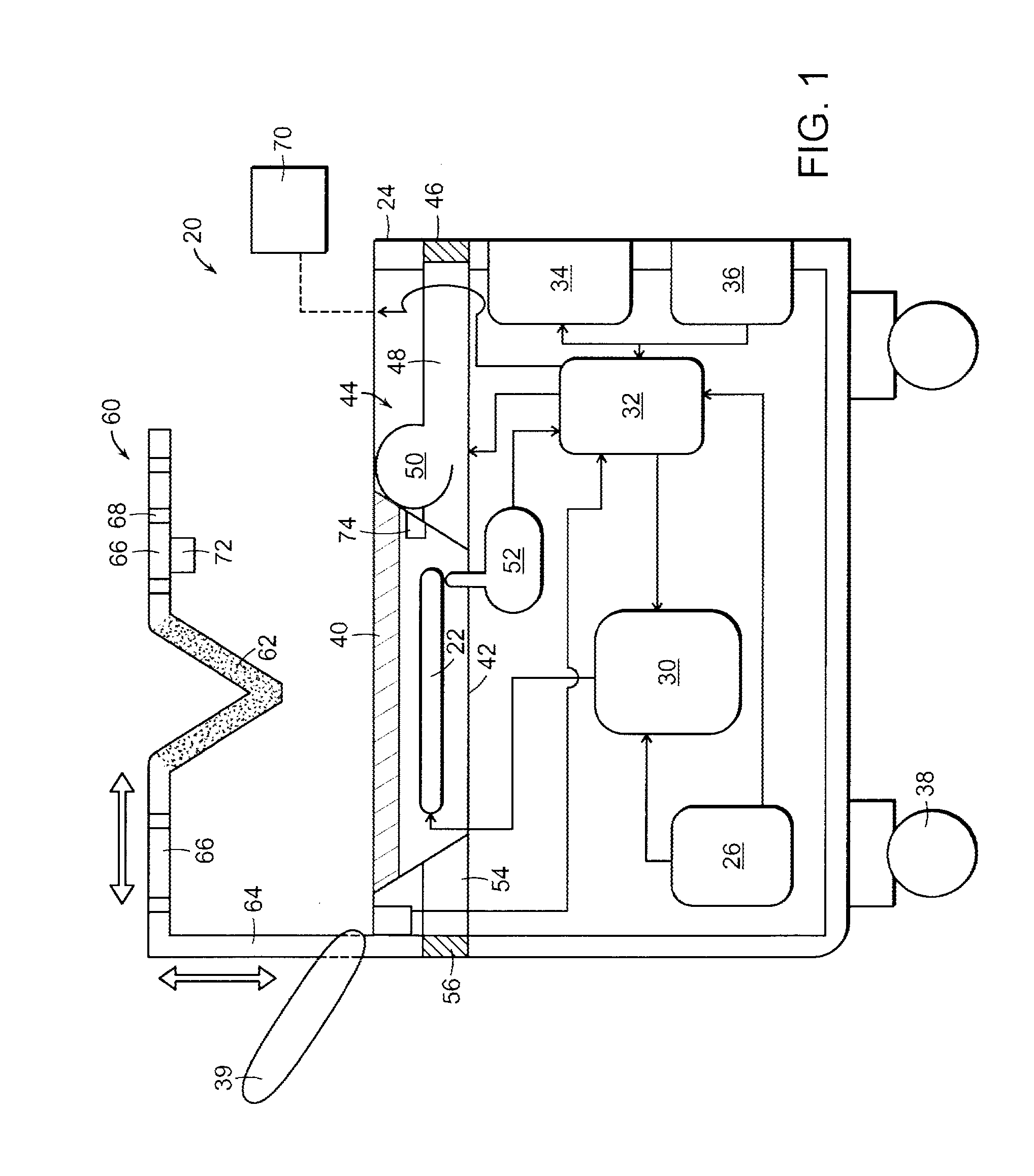
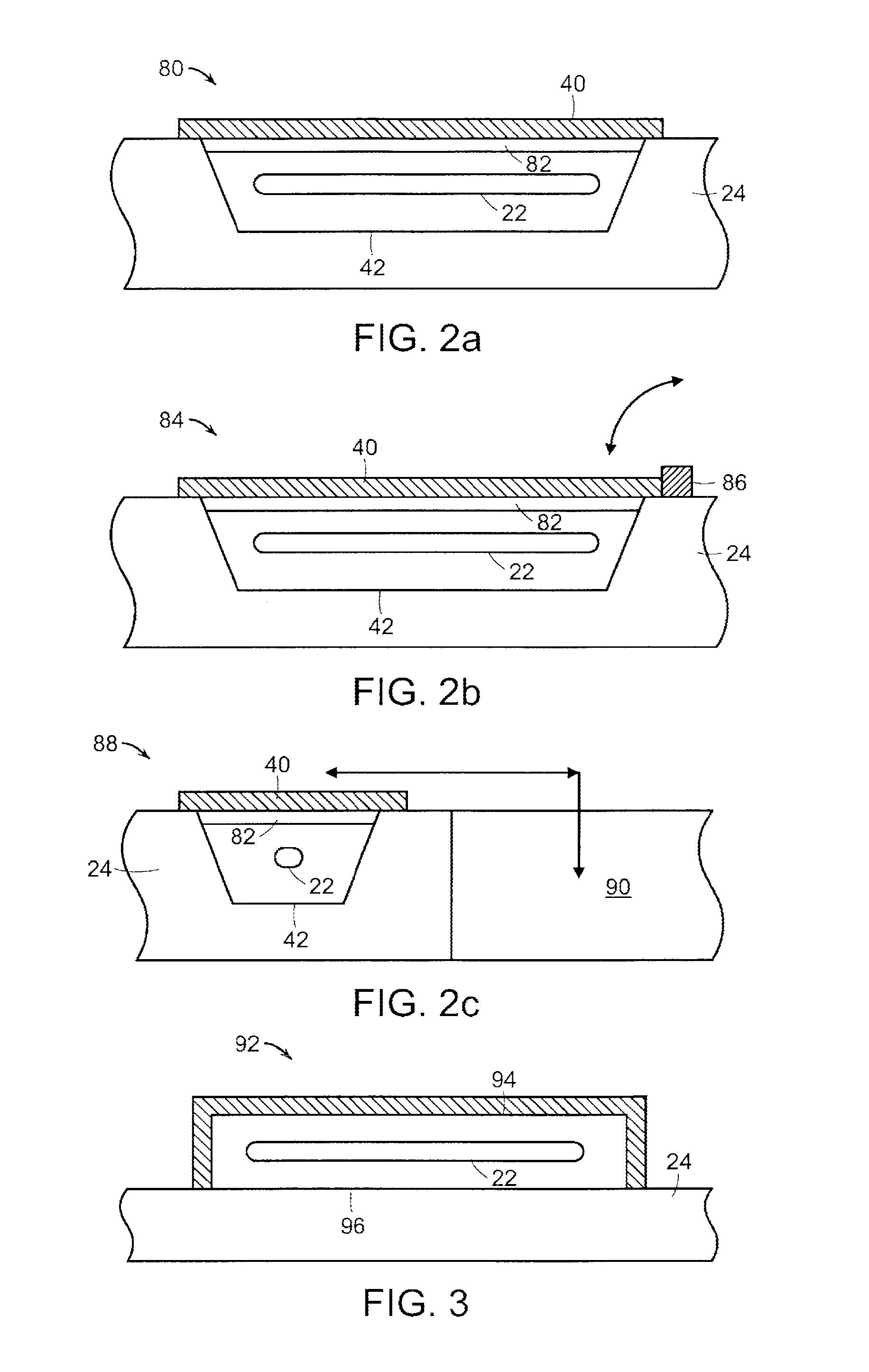
[0036]Turning to the drawings, exemplary embodiments of discharge lamp apparatuses are provided. More specifically, exemplary configurations of apparatuses are shown in FIGS. 1-3 having a discharge lamp arranged lengthwise parallel to a plane of the apparatus at which the lamp is supported (hereinafter referred to as a “horizontally positioned lamp”). In addition, exemplary configurations of apparatuses are shown in FIGS. 4-8 having a discharge lamp arranged lengthwise perpendicular to a plane of the apparatus at which the lamp is supported (hereinafter referred to as a “vertically positioned lamp”). In addition, a system having two discharge lamp apparatuses is shown in FIG. 9. As will be set forth in more detail below, the apparatuses and features described herein are not limited to the depictions in the drawings, including that the discharge lamps are not restricted to “horizontal” and “vertical” positions. Furthermore, it is noted that the drawings are not necessarily drawn to s...


PUM


Abstract

Systems are disclosed which include processor-executable program instructions for receiving data regarding characteristics of a room in which one or more disinfection sources are arranged and determining, based on the received data, individual operating parameter / s for the one or more disinfection sources. Other systems are provided which include processor-executable program instructions for discerning, for each of a plurality of disinfection sources, a target location, region, object or surface within a room in which the disinfection sources are arranged. The systems further include program instructions for comparing the target locations / regions / objects / surfaces and executing corrective actions upon detecting two or more locations / objects / surfaces are within a predetermined distance of each other and / or upon detecting two or more regions overlap.

Description

CONTINUING DATA[0001]The present application is a continuation-in-part from pending International Application No. PCT / US2012 / 041483 filed Jun. 8, 2012, which designates the United States and claims priority to U.S. application Ser. No. 13 / 156,131 filed Jun. 8, 2011.BACKGROUND OF THE INVENTION[0002]1. Field of the Invention[0003]This invention generally relates to germicidal devices and, more specifically, systems which determine operating parameters and disinfection schedules for germicidal devices and further germicidal lamp apparatuses including lens systems.[0004]2. Description of the Related Art[0005]The following descriptions and examples are not admitted to be prior art by virtue of their inclusion within this section.[0006]In general, germicidal systems are designed to subject one or more surfaces and / or objects to a germicide to deactivate or kill microorganisms residing upon the surface / s and / or object / s. Applications of germicidal systems include but are not limited to ste...

Claims


Application Information

Patent Timeline
IPC IPC(8): A61L2/24
CPCA61L2/24A61L2/10A61L2202/25A61L2/06A61L2/07A61L2/14A61L2/20A61L2/22A61L2202/14G16H40/20A61L2202/16
Inventor STIBICH, MARK A.CARPENTER, P. KEVIN
Owner XENEX DISINFECTION SERVICES
Learn More